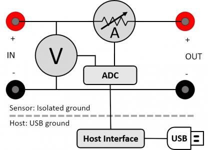
Hi @Kart and welcome to the forum! Yes, it is possible to use Joulescope to measure higher voltages using a resistive voltage divider with some caveats. Here is a simplified block diagram of your Joulescope:

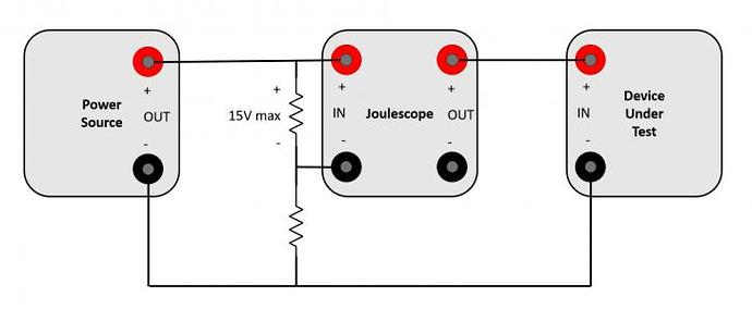
The IN- and OUT- are actually tied together inside Joulescope (actually on the front panel). If you can tolerate drawing a little extra current from your source, you can use a resistive voltage divider. Connect the resistive voltage divider between your power source - and +. Size the resistors so that the voltage from power source + to the divided voltage node does not exceed -15V. Then connect the divided voltage node to IN-. Connect power source - to your device under test’s -. Here’s a diagram:
You still need to ensure that no IN or OUT signal is more than ±48V from USB GND. Although Joulescope’s sensor side is isolated from the USB side, Joulescopes are only certified for low-voltage use. Joulescope’s voltage and power will be off by the same factor as the voltage divider.
As an aside, although Joulescope only measures -1 to +15 V, it is specified to tolerate ±20V.
Does this work for you? If you cannot tolerate the extra current from the resistive voltage divider in your setup, there next best option is a battery-powered op-amp buffer followed by the resistive voltage divider.
