Hi! I have been using the Joulescope for quite some time for testing IoT devices. Recently, I needed to test the charging of a tiny battery inside of a device we’re building. I figured the Joulescope could do this.
I planned to connect the battery management circuit (charger/discharger) to the input side and the battery to the output side. I knew there was going to be some reverse current, because the battery is also discharging but this wasn’t important for the measurement and from consulting the datasheet it didn’t seem like the Joulescope could get damaged. I tried powering a LED on the reverse channel beforehand to test the reverse measurement, everything worked fine.
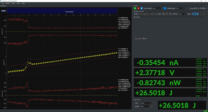
I had trouble measuring the battery, the voltage measurements were all around the place. Later I noticed weird behaviour from the Joulescope. This is a screenshot of the oscilloscope view after startup:
It seems like the scope is charging itself and slowly drifting from 0 to 5V or even 10V. If I put a load (any load) on the output or simply short the output (with no input) this corrects to 0. If I connect a source and load the measurements seem perfectly fine. The current reading seems unnafected whatsoever. But the voltage still drifts with no load.
I don’t understand what is causing this, maybe there are some capacitors charged on the load side? Did I damage the device? Is there any way to fix this? Thanks.
Hi @Jakub_Nagy and welcome to the Joulescope forum. If I understand correctly, you are observing the voltage with nothing connected to either the Joulescope input or the Joulescope output. The voltage drift you are seeing is normal and expected in this case.
Your Joulescope has extremely high input impedance. The front-end of your Joulescope’s voltage measurement uses an opamp. This opamp has a small input bias current, ± 20 pA max at 25 °C. When the voltage input is floating, this current is pulled from the parasitic capacitance, which charges up. Depending upon the parasitic resistance, it may charge all the way up to the + or - voltage measurement limit. So, your Joulescope is measuring a real, if non-intuitive, voltage on its input.
Most test equipment limits this behavior by intentionally adding resistance to the input, often 1 MΩ or 10 MΩ. We intentionally did not do this with your Joulescope JS110 since many of our customers care about nA of current. If this behavior bothers you, you can add a resistor between IN+ and IN-. However, as soon as you hook your Joulescope up to a real circuit, it will easily supply the bias current. Your JS110 will correctly measure the voltage from IN+ to IN-, and this added resistor will only cause extra current consumption.
Does this make sense?
1 Like
Oh I see, this makes sense. I never noticed a drift before with nothing connected, only noise. But I wasn’t paying specific attention to it before either. So today I panicked thinking it was related to the previous measurements.
Adding the resistor makes sense, but I also care about nA so I won’t be doing it if I know the measurements with a load will be correct.
I’m still not sure why measuring the battery charge discharge didn’t work as expected. It worked with a supercap. So I’ll try to fix the connections and charger, I’m happy to hear that I don’t have a problem with the scope.
1 Like
If current looked correct, it is possible that IN- or OUT- was not connected to your circuit. Note that your JS110 shorts IN- and OUT- together on the front panel.
If you still see this voltage drift behavior when your circuit is connected, please post again. I’m happy to help figure out what’s going on!
Great, thanks for the help!
