During external ESD testing on our product to assess its impact on internal PCBs, I used an ESD gun to discharge 16 kV on the casing without the joulescope connected. Subsequently, I connected the joulescope to monitor any changes in sleep current. Despite repeated tests, the most recent attempt appeared to damage the joulescope. Following the ESD event, plugging in the JS110 resulted in a switch-like click sound. Now the joulescope displays a single value, as depicted in the attached screenshot. This value is fixed, and I can’t seem to alter it in any way. The joulescope still succeeds in operating and providing power to the device but does not give any correct readings on the joulescope software. Any insights or suggestions on resolving this issue would be greatly appreciated.
Hi @Marf - Sorry to hear your JS110 was not able to take the 16 kV beating. While the JS110 did pass CE testing with 8 kV, I don’t think we did any testing at 16 kV. Despite passing the CE testing, the JS110 always did seem to have more ESD susceptibility that we would have liked. The combination of high bandwidth, nA sensitivity / leakage, and great ESD supression is very challenging. That said, the JS220 has much, much better immunity than the JS110!
I really don’t like the “switch-like click sound” description since the JS110 has no relays. We have had a handful of failures with C116 and/or C120 that seem to be ESD-related. See the Joulescope JS110 User’s Guide section 17.4 on page 40 which has instructions for identifying and fixing this issue. Is this the problem with your JS110?
That seems like it may be the issue. Although the voltage readings are -16V, I am reading 4.5kohms across them. I will attempt to replace them. Thinking ahead, if that doesn’t resolve this, is there anything else it might be?
I replaced the capacitors on the broken JS110, but I still am getting a reading of 4.5K ohms. To double check, I measured the resistance of the capacitors on our other JS110 that still works. Those values were also 4.5k ohm. The guide says they should be higher than 10k. Do you have any thoughts on this? I have ordered the three different types of FETs as the next step of troubleshooting from section 17.3.
Sorry to hear that didn’t work. The 4.5 kOhms could be OK. Measuring resistance in-circuit is always challenging. If your multimeter uses a slightly higher voltage, then it will measure more “leakage” current through the active circuitry. Since you were still seeing -16V and you are measuring the same resistance after swapping the capacitors, it’s safe to say that these caps were not the issue.
Before you start swapping MOSFETs, have you performed the diagnostic described in section 17.3 to manually select each current range? Do you find one range that is bad and the rest are good?
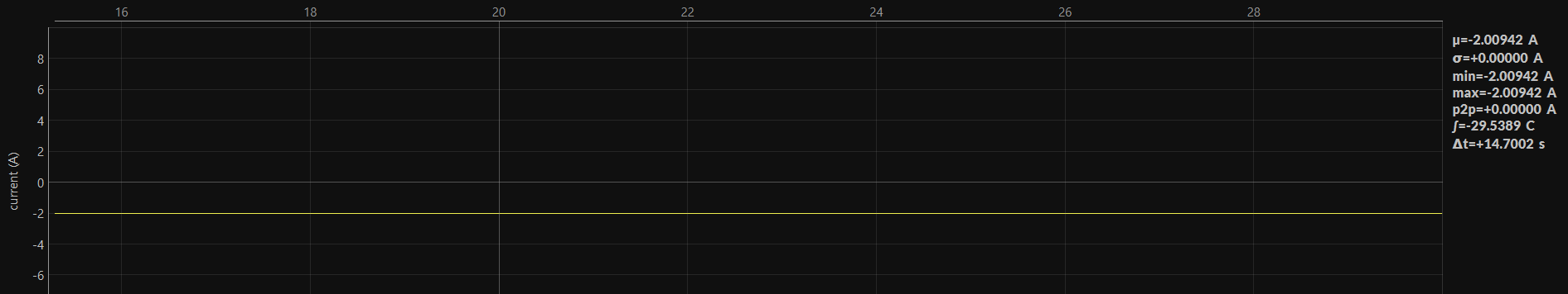
All 7 ranges given in 17.3 and described in 8.5 were extremely off. For example, the current range of 10A gave a reading of -2A, should have been close to 1 mA.
It is very unlikely that all MOSFETs failed. If all of the current ranges are extremely off, then it is likely something else.
My next guess would be either a power rail failure or the voltage reference failure. While diagnosing the issue is not too problem, figuring out what failed is very difficult and likely not worth the time.
If you want to check the power rails, have the Joulescope JS110 running and carefully measure the voltage (do not short anything out) across the following capacitors:
C25: 3V6 analog
C36: -1V5 analog
C57: 3V3 reference
C76: 3V3 digital