Dear community,
I am currently investigating an issue in a device and I am looking into measuring the current flow and voltage levels in a signal line instead of power supply. This would be especially for monitoring purposes, since I am not quite sure what the root cause of the issue with the device is, since I only have incomplete information on how the device was handled before running into the issue.
So my question basically is the following:
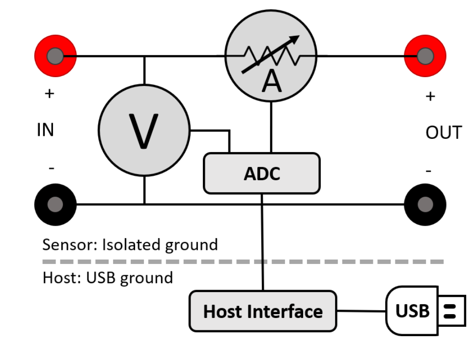
Could I just connect the JS110 between the output of one IC (Line driver/signal buffer) and the input of the other IC (Schmitt Trigger as Buffer. The signal would obviously go from the output buffer into the IN+ and then from the OUT+ to the input of the next IC.
I could then either connect the OUT+ and OUT- together and leave IN- unconnected, but then I would not have any voltage reading on the signal anymore, which would be unpractical, because there might be a short somewhere to a higher voltage which potentially leads to the destruction of the device.
But I guess since the IN- and OUT- are anyway shorted together, I could also connect the Device Ground with the to have the ground reference for the voltage measurement in the JS110 correct?
I am sorry if this description is incomplete in some parts. I am happy to answer further questions of the setup for clarification.
I am also curious if anyone already performed such measurements and if its practical in any way.
Best regards,
Alex