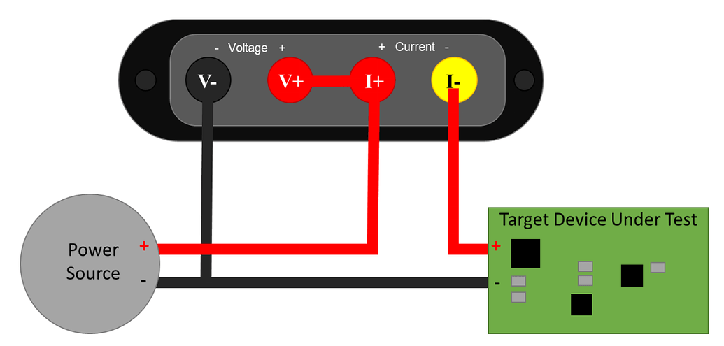
I have a target board with ESP32 and I am using Joulescope in this configuration
Power Source :- 3.7v LIPO Battery
So when I run my device without Joulescope it runs fine. But when I connect to see the current in the given configuration then my board does not run.
is there any different settings needed for this case?

Hi @hallotronix and welcome to the Joulescope forum!
By default, you Joulescope JS220 disconnects I+ from I-. In order to allow current to flow, you must connect to your JS220 from the host computer and enable a current range. The easiest way is to launch the Joulescope User Interface.
Have you started the Joulescope UI with the Joulescope JS220 connected?
If you have started the UI and you are still not able to power the target device, can you answer a few questions:
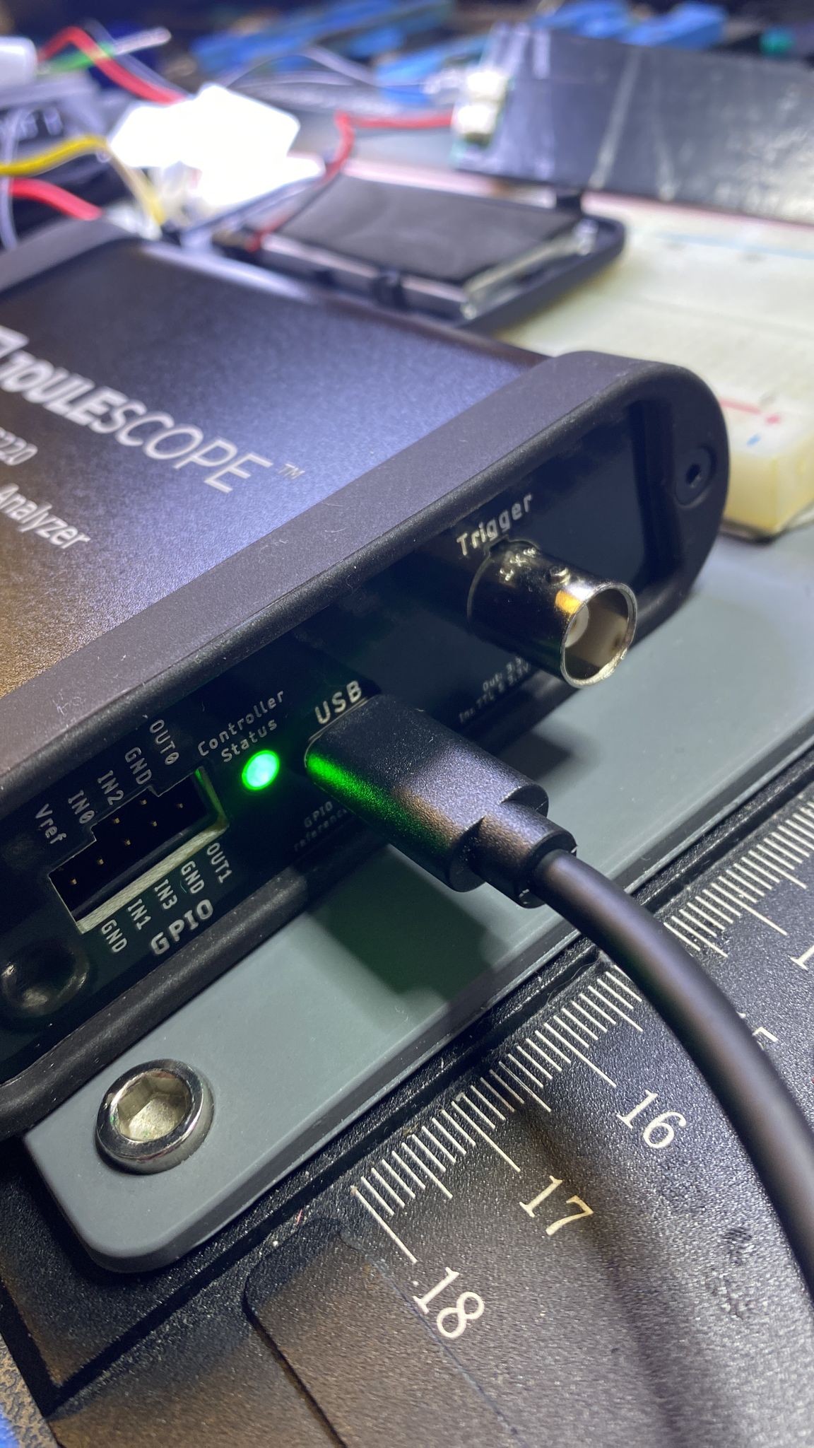
- What is the color of the Controller Status LED?
- What is the color of the Sensor Status LED?
- Do you see sensor data displayed in the UI?
Where in User Interface we have this option?
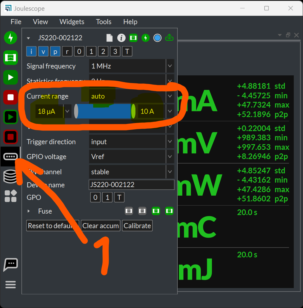
When you start the Joulescope UI, it should automatically configure the current range to auto, which connects I+ to I-. Unless you have changed the defaults, it should just work. Here is how you can double check:
If you do not see data in the Multimeter widget and the device is not present in the Device Control widget as shown, then that indicates a problem.
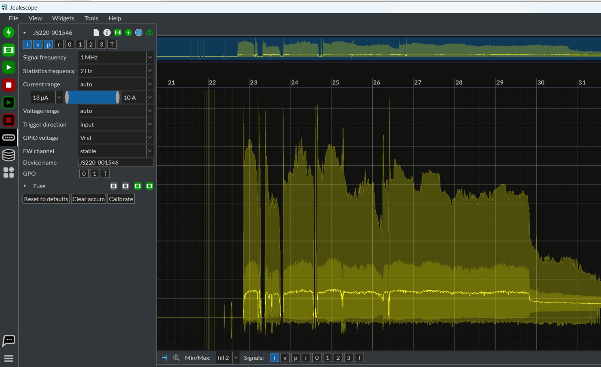
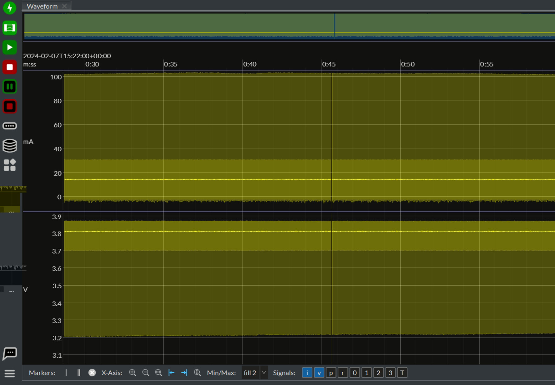
Thank you for the screen capture and images. Your Joulescope JS220 certainly looks to be running correctly. The Waveform widget even shows some current flowing through the JS220 from I+ to I-.
I suspect something with your setup is not connected.
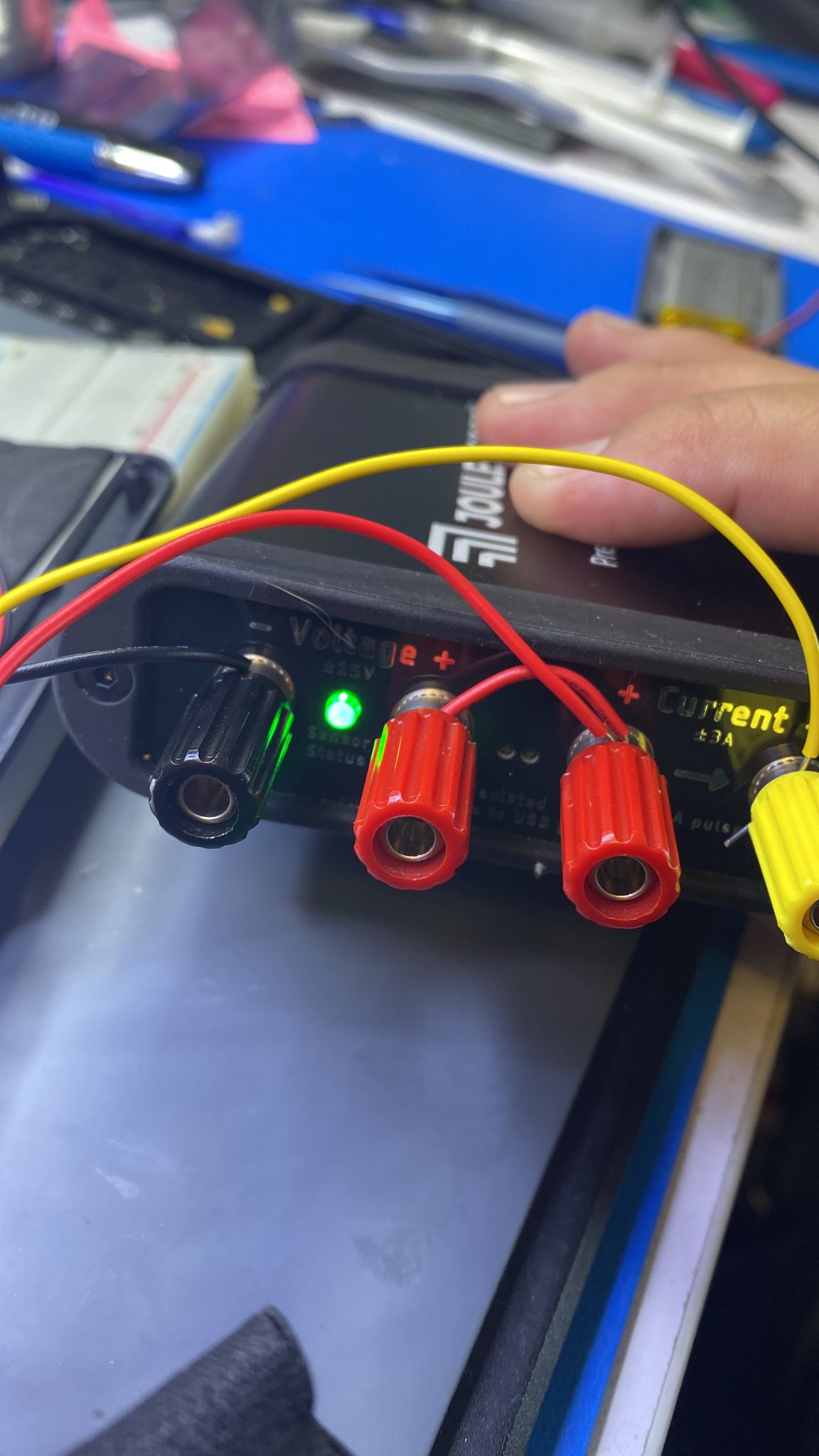
- Can you confirm that the LiPo battery negative goes to both V- and your target board?
- Is anything else connected to this system?
- If you set Current Range to 10 A rather than auto, does that change anything?
So here is voltage I can see. but my board is not Running as I can see it’s not generating 3.3v out of battery if connected via Joulescope using the way I shared in first post.
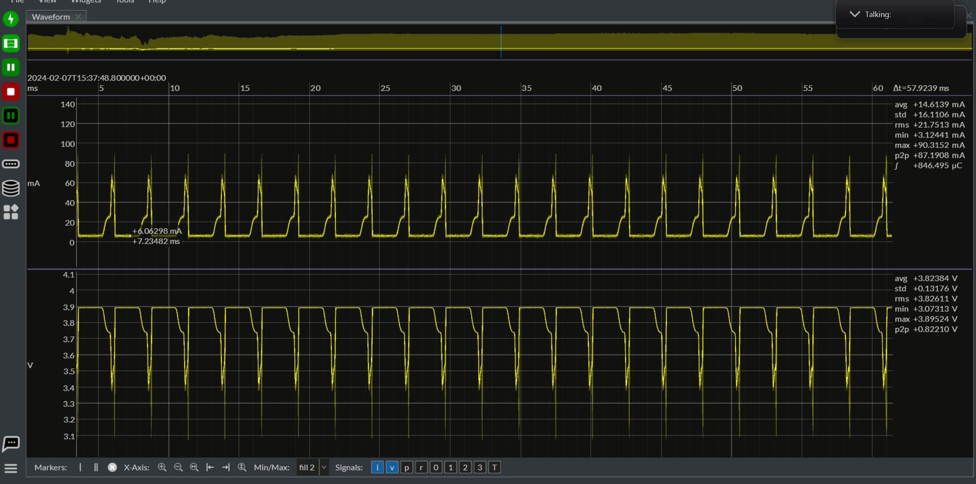
Can you zoom into that captured data and post another screenshot?
I think you are saying that everything is connected correctly and your board is getting voltage and current. However, your board has a DC-DC converter that is not regulating correctly. Did I understand correctly?
- If you set Current Range to 10 A rather than auto, does that change anything?
– I see some difference. - Is anything else connected to this system?
- You mean to the board or Joulescope? Nothing is connected to Joulscope other than my Board.
- Can you confirm that the LiPo battery negative goes to both V- and your target board?
– Yes, Just cross checked this and it’s connected exactly this way.
So now. I see that my Board is getting started but keeps rebooting now. Without putting joulescope in between it is working fine. No Rebooting. – This is weird this is not happening everytime… This happened only when I take my multimeter and tried to measure voltage and I see my board started rebooting. If i do not do this then board does not get ON.
Is this the correct way to measure current or I am still missing any settings in Joulescope?
Yes, This is exact my issue.
From what you described, you have the connections correct. There are no additional Joulescope settings that make this different.
I suspect that your target board has a DC-DC converter that is already marginally stable. When you connect in Joulescope, you add additional impedance from the cables and the JS220. The JS220 only adds 20 mV drop maximum, but can vary from 0.01 Ω to 1000 Ω. By putting your Joulescope into the fixed 10A range, you forced your JS220 to use the 0.01 Ω resistor. However, the wires and any other connectors add resistance and inductance.
-
Does your target device have adequate input bypass capacitance for the DC-DC regulator? Assuming that you are using MLCC capacitor(s), be sure to derate the capacitor for the operating voltage. You may need additional input capacitance for proper DC-DC regulator operation.
-
You can reduce the impedance of the wires. Here are some tips:
a. Keep the wires short.
b. Twist together the + and - wires to minimize inductance.
c. If you have any wire connections that are twisted together, use a better method like solder, crimp, or connector.
Well, I am not sure if I needed that as it was working fine if I do not have to use it the way current measurement needed. But let me check that out as well.
Wires are very short so twisting is not done on this as it’s not long enough to twist properly.
Other than the LiPo battery, the target device, and the JS220 (with isolated USB connection to the host computer), is anything else connected to this test setup?
If you can share a picture of your full test setup, I am happy to take a look to see if I can spot anything else. Feel free to blur out or scribble over your target device if that is sensitive, but please clearly show all connections.
Ok, Give me few mins. I am going to share in couple of mins. Also this time I tried external power source and I saw same result with 4.15v which is very much in range of DC-DC converter.
Sharing whole setup photo very soon.
Thank you for quick answers @mliberty I really appreciate help here.
- I can not add any more reply to this forum it says wait for 22hrs. can you do anything @mliberty ?
Update:-
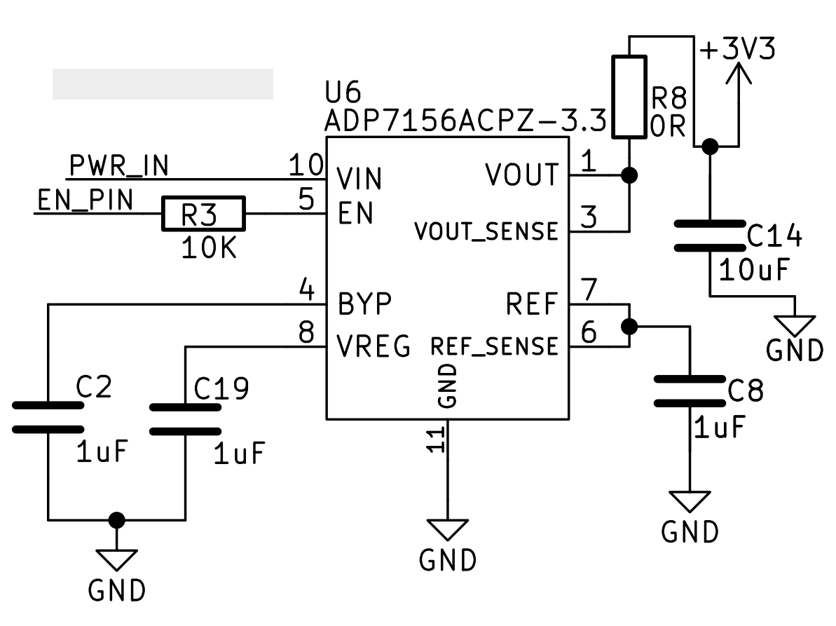
Here is DC-DC Converter
1 Like
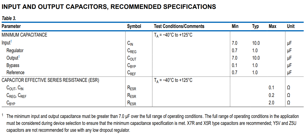
Does this target device also have 10 µF on VIN? From the ADP7156 datasheet:
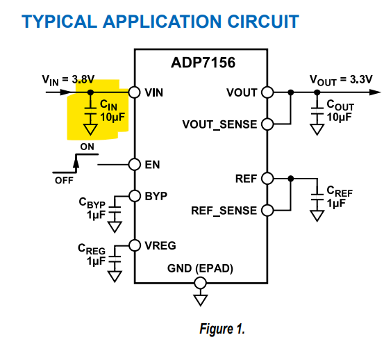
Yes, It has another section of the schematic.
Update:- When I connected Power Supply external and set voltage to 4.17v then I got my board running.
I think instead of battery I should use this power supply for current monitoring. Not good way but I think this is what have to deal with for now.
You can certainly use an external power supply.
If this target device is a product under development, it’s likely worth the effort sometime soon for you or someone else on the team to figure out what is going on. Nothing about the JS220 should cause this behavior, which likely indicates that the target device is marginal. It’s better to figure out why sooner before having lots of deployed units that start exhibiting this same issue!
Here are some questions to consider:
- Is that ~5 millisecond cycle time in the zoomed in screenshot your device rebooting?
- Is the brief drop of the LDO input to 3.1 V enough to brown-out something on the device?
- If you short JS220 I+ to I- without changing anything else, do you still see this problem? This bypasses the JS220’s internal impedance but keeps the wiring the same.
- Does the design follow all layout guidelines for any & all DC-DC regulators? For example, see the “PRINTED CIRCUIT BOARD (PCB) LAYOUT CONSIDERATIONS” in the ADP7156 datasheet. The fact that the input capacitor is on another sheet makes me concerned that it is not routed close to the ADP7156. Also, the addition of the 0 Ohm R8 can make layout worse.
- Did the design correctly derate these capacitors for working voltage? Are they still within spec?
- If you use an oscilloscope to measure the VIN and VOUT voltages during startup, how does it compare to battery only vs battery + JS220?
I hope the JS220 helps you create something great!
I will answer these questions. Give me sometime so I can finish out current ongoing tests.
! Making sure that I will keep following this topic and answer all in some time.