Joulescope’s voltage display shows the voltage on the load side of the shunt, but for purposes of measuring battery internal resistance it’d be handy to be able to see the source voltage. Battery resistance could even be automatically calculated and displayed at marker locations.
Hi @JuliaTruchsess,
Your Joulescope measures voltage on the input side from IN+ to IN-. See the first figure in the “Theory of Operation” section in the Joulescope User’s Guide (currently page 19). However, the measurement is really between IN+ after all front panel and main/front panel connector losses, and IN-, but with approximately half of the front-panel PCB losses to OUT-.
Joulescopes connect IN+ to OUT+ through the variable shunt resistor and a MOSFET. However, additional resistive losses occur in the IN+/OUT+ connectors, the front panel traces, the main PCB to front panel connector, and the main PCB traces. Joulescopes connect OUT- to IN- on the front panel, so the only losses are the OUT-/IN- connectors and front panel traces.
I’m not sure that I am total following the suggestion about the software displaying battery resistance at marker locations. Are you saying that the user would select several (>= 2) different regions of varying current consumption, and Joulescope would estimate battery resistance by solving for Vbattery and Rbattery:
Vmeasured = Vbattery - Imeasured * Rbattery
Note that Rbattery calculate this way will include all cable and connector resistances.
Oops, I just assumed (yeah, I know…) that it measured on the load side in order to give the most accurate measurement possible of EUT power. Sorry for not RTFM’ing.
Yes, I had in mind identifying two points and having the scope calculate (V1-V2)/(I2-I1):
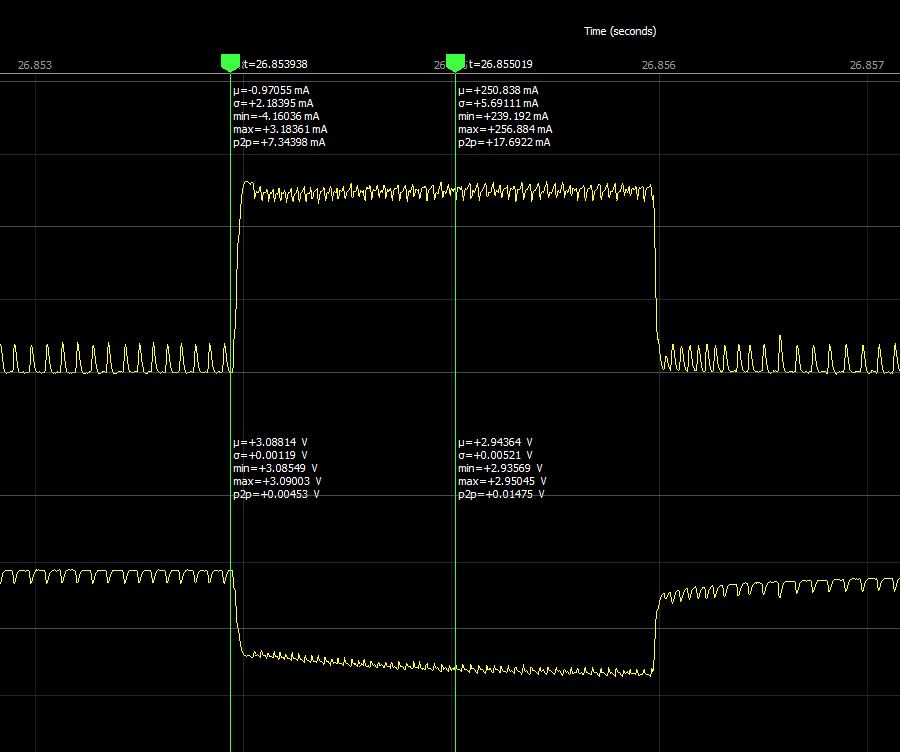
(574mΩ in the example) but you’re right - it’s maybe not so useful given all the error sources. Really should be a 4-terminal measurement directly on the battery terminals, which in this case gives about 278mΩ. Of course, once you know all your contact and lead resistances… ![]()
1 Like
Leaving aside any attempts at “automatic” source resistance calculation, it would probably still be useful in many situations to have Joulescope display the delta (current, voltage, power, etc) between a pair of markers.
The y-axis delta between two x-axis markers is a little weird, but certainly possible. Do you really want y-axis markers?
I could also see a y-axis marker that is locked to an x-axis marker. It’s y position would change to track the mean, min, or max at the x-axis marker’s position.