Hi sir, good evening
this is the below BLE device use case
iam not getting clearly what is the issue the client is asking / pointing out.
can you please help me in this regard.
please find the image below.
Hi sir, good evening
this is the below BLE device use case
iam not getting clearly what is the issue the client is asking / pointing out.
can you please help me in this regard.
please find the image below.
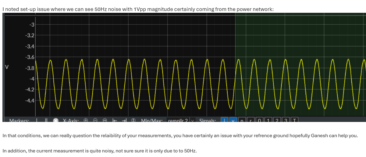
Hi @NGS - For battery powered devices, the voltage should normally be a constant value. You chopped of the x-axis and statistics from the image, which would have been helpful. I cannot comment on frequency. Peak-to-peak appears to be about 0.9 V.
It is very common for test setups to pick up mains frequency noise, especially if you do not consider wiring and connections. Joulescopes are designed to not couple any mains or USB noise into your measurements, so it’s likely some other cause. In general, you want to avoid ground loops. reduce loop area (keep connections short and twist supply & return wires together), and remove other test equipment & connections from the setup. Start with just power source, Joulescope, and target device. Make sure that you connect Joulescope Current+ to Votlage+. Does this noise go away? Then add in whatever else you have and see where the noise starts.
Hopefully these general tips help. Noise pickup is very dependent on the test setup. If you want more specific help, please provide a diagram of the test setup and pictures.
Hi sir good afternoon,
First point :
this -ve voltage with 1vPP we got due to joulescope voltage terminals were left open, and saved the UI file with Voltage enabled.
sorry for wrongly interpreting you , without checking how the test setup was connected.
second point :
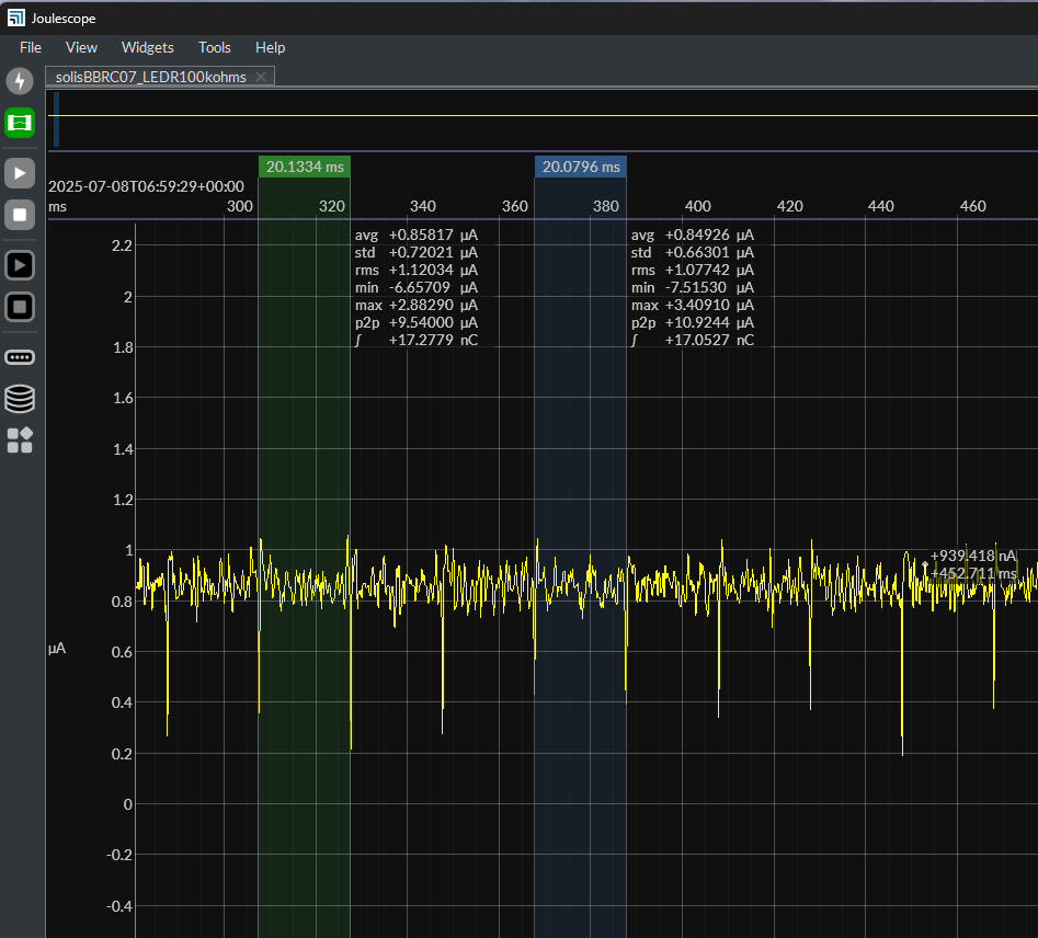
regarding noise in the current profile.as below i see thier is a signal for 20msec/ which i see due to supply frequency 50 hz, is this what iam going in right way,
3rd point :
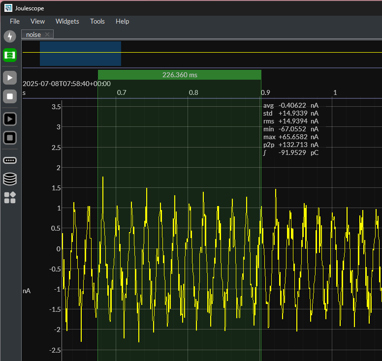
i have recorded current profile of joule scope, with all terminal open ,without any connection.
please go through the joule scope UI file
can you please verify my joulescope is working properly , is this the expected profile.
Hi @NGS
Yes, you need to connect the JS220 voltage terminals to make any meaningful measurement. Please see “How to Connect Your Joulescope” in the Joulescope JS220 User’s Guide for common setups.
One person’s signal is another person’s noise. Your Joulescope measures current and voltage. You need to create a test setup that present the current and voltage you want to measure. It is really easy to create a test setup that picks up other electromagnetic signals, including mains, lighting, motors, speakers, and to a far lesser extent RF signals like Wi-Fi, Bluetooth, and mobile. The information you have shared is insufficient for me to help identify what is happening. Please share a 1 Msps full rate JLS file including the “r” (current range) signal. 60 ms duration should be enough.
Again, this looks like 50 Hz mains signal that you are picking up with under 4 nA p2p. That is a small signal, and your location seems to have pretty strong mains emissions. You also have a bunch of other noise pickup with about 15 nA std and 133 nA p2p. All wires are antennas, even the binding posts on your JS220. When you start caring about nA, you will find a whole bunch of strange contributors that create “unexpected” signal. You have already seen undesireable electromagnatic pickup. Other effects include junction voltages, piezoelectric, leakage currents (require guards to mitigate), stray inductance coupling, and capacitive coupling.
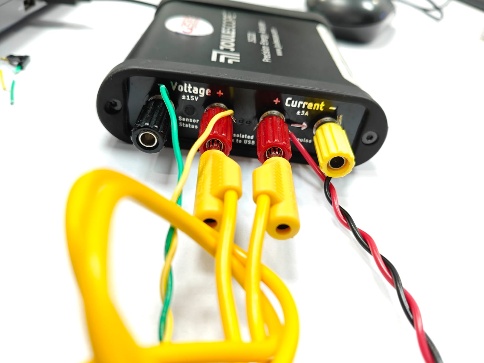
In the image you shared, that yellow wire between Current+ and Voltage+ looks like it could be a really nice loop antenna. I can’t tell how it’s wound, though. Regardless, you seem to care about nA, which means attention to detail in the test setup. How about using a very small piece of wire directly between Current+ and Voltage+?
hi sir,
good morning
thanks for the feedback,
please find the UI file below of BLE advertisement, please check.
1)
adv_70msec_with_i_r.jls (285.4 KB)
thank you.
Are you sure this is the right file? It only contains i (no r) and does not look like a BLE advertisement.
It’s a little more noisy than expected, but your location looks to have higher noise. Here is what I see: i_disconnected.jls (285.4 KB)
Hi sir,
firstly sorry for late reply.
point 1:
yes sir, you are right , please find the below file for BLE_ADV with ‘r’ included.
please go through it , please share you comments if any noise in my BLE adv profile ;
actually iam not getting how the noise pattern appears and how to mitigate it effectively.
iam trying to follow some joule scope manual instructions, to reduce the noise effect.
please find the below UI file :
ble_adv.jls (657.8 KB)
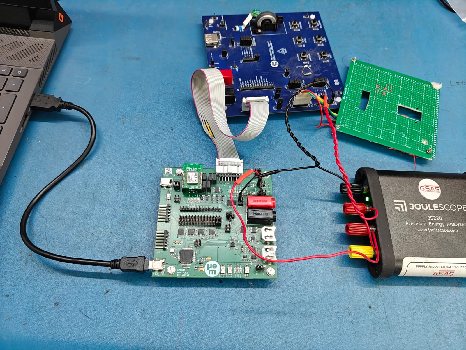
please find the setup image :
point 2:
i sent this to understand how the noise in our signal present ; what is the level of it, what measures to be taken to reduce it.
point 3:
i have gone through manual of joule scope & noted mainly 4 configurations.
1) Measure current only (Ammeter ) // understood okay
2) Measure voltage only (Voltmeter) // understood okay
3) Measure power supply provided
when we connect in this configuration , we will be reading/measuring the voltage & current starting at the source point.
is this correct what i understand ; please correct if am going in otherway.
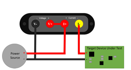
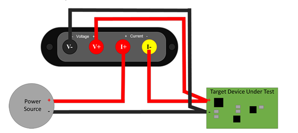
4) Measure target device consumption
please confrim my point. 3& 4 understanding.
Hi @NGS - thank you for the picture. I am not quite sure what I am looking at. Are you using the EM9305 board to supply power to the other two boards? When twisting wires together, you want to twist together wires with the same current, such as supply and return.
For config (3), you twist PS+ and PS- to the JS220. Then you twist together V- and I- to the target.
For config (4), you twist together PS+ and PS- to I+, then continue with PS- and I- to the target. You then twist together V+ and V- from the board.
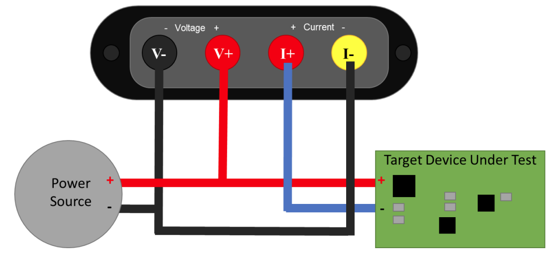
The difference between (3) and (4) is where you measure the voltage. (4) can measure a regulated voltage or ignore voltage drop across the wires, commonly known as “Kelvin” style connections. For your current levels, Kelvin style connections will likely not matter and config (3) and (4) will likely yield the same measurements.
hi @mliberty
thanks for the reply.
for config 3 & 4 you are describing the the twisting of wires between source/joulscope/DUT
is this the way we need to follow ,
or you are pointing how we did on our test setup.
please confirm.
can we know for what range of currents/ voltage / use case , will have a impact when we choose config3(source side high end )connection & config(4) low side connection.
i mean to ask when we can see the difference between config3 & 4 connections used.
please confirm.
Section 9.3 of the Joulescope JS220 User’s Guide shows how to make a low-side measurement:
Joulescopes have the same accuracy in both high-side and low-side configuration. However, low-side configurations have more possibility for ground loop issues, so it is normally easier to use a high-side measurement.