Hi,
I just got my Joulescope yesterday at work and played around with it for a few hours.
I was very impressed as I’ve been waiting for a tool like this for years.
One of our major products is a wireless transmitter and was eager to get some proper power readings without having to keep switching resistors and messing with the software to measure the current.
The Joulescope worked fine and I thought I would bring it home to play over the weekend. I had the same setup as I had at work and it was working OK until at some point it started giving me strange readings.
Our board goes from about 16uA in sleep up to 150mA when transmitting and I was seeing this at work and first the first hour playing at home. But then for no apparent reason it started showing the sleep current as 1.3mA and the transmit current at 5mA.
I know these numbers can’t be real as the radio has a fixed transmit power and it was still transmitting OK. No software or the hardware hookup had changed.
When it is asleep I can change to the fixed range and it does show the 16uA reading. So something must have gone weird with the auto ranging.
I’m powering this from 2 AA cells so it’s not a power supply issue either.
Anyone else seen this?
I will of course try this at work on Monday in case something weird happened with the software or my PC at home. But I also tried the Linux version at home too and it showed the same.
I do hope it isn’t a faulty unit and I have to send it back. I really want to get to using it after its long anticipated arrival!
Anyone have any ideas to try to resolve this?
Many thanks.
Liam.
Hi @Ldr1970,
Welcome to the forum and thanks for backing Joulescope. Sorry to hear that your Joulescope is behaving oddly, and this is not something I have heard about from anyone else yet. I do know of an autoranging issue (I am currently working on a fix) that could potentially cause some units to behave slightly differently, but I don’t think that it explains what you are seeing.
Would you mind helping me troubleshoot this issue? Here is what I would like you to try:
- Disconnect everything from your Joulescope. Start the Joulescope software and verify that the current is 0 A (should be within 10 nA nominal 30 nA max)
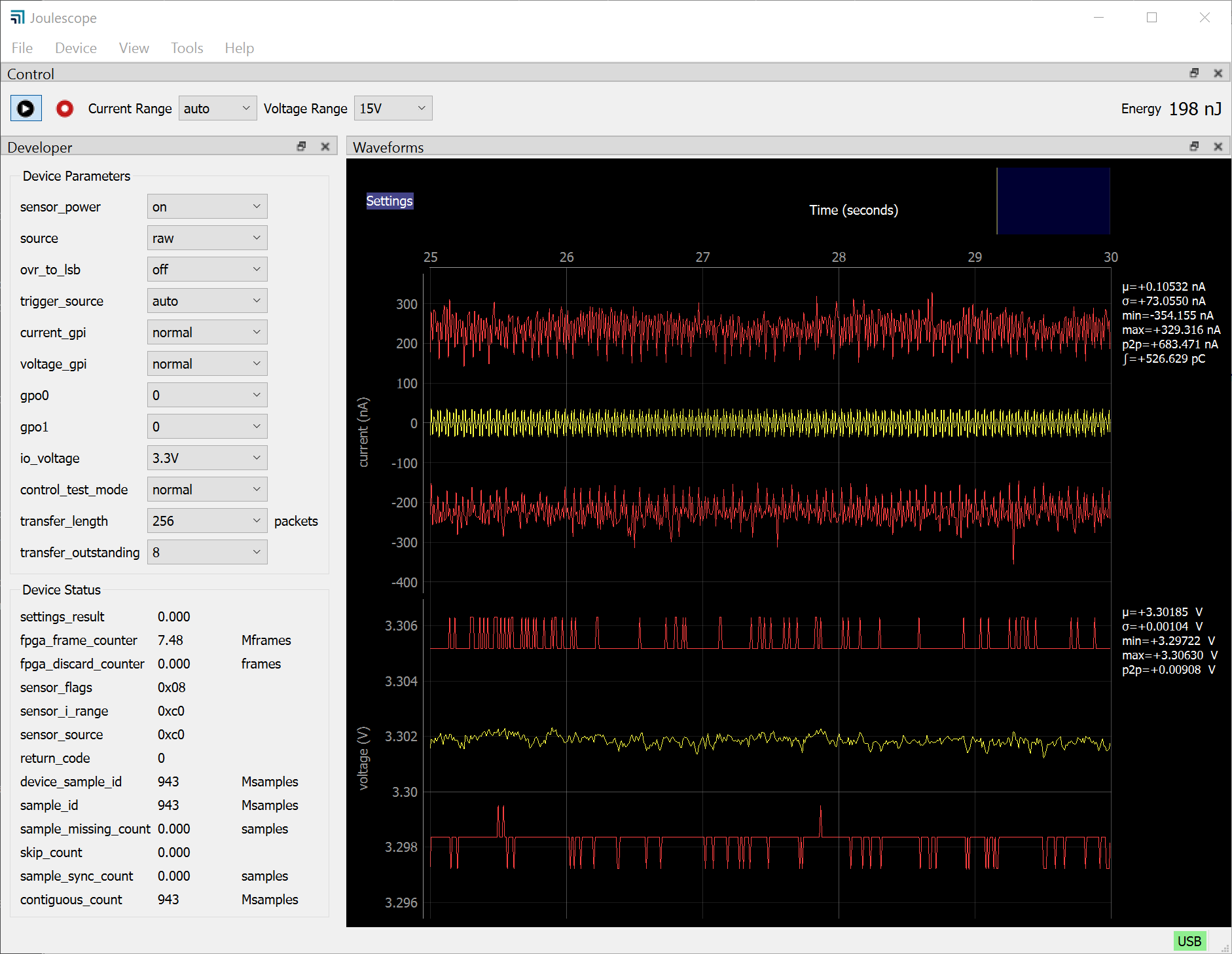
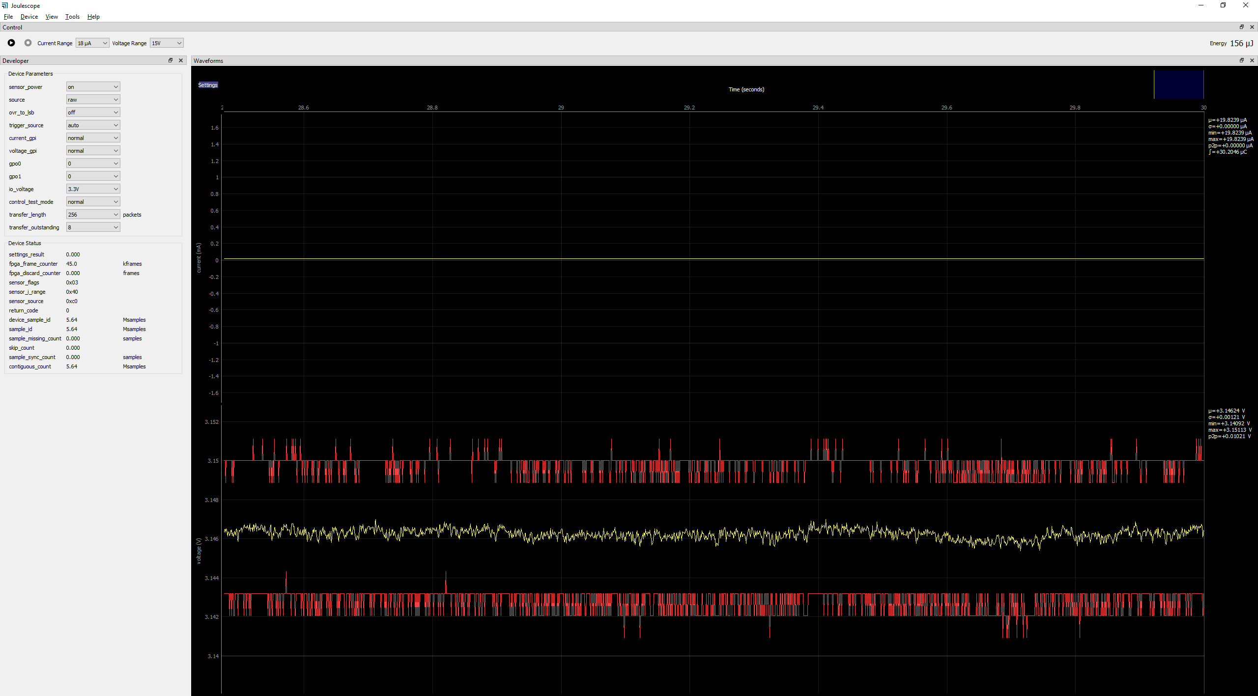
- Connect your system back up. Bring up the oscilloscope view, and add the developer view (View Developer). Copy a screenshot (you can use snipping tool on Windows) and paste to this forum. Here is what I see with no load and 3.3V source:
The main thing that I want to see is sensor_i_range. If sensor_i_range is not 0xc0 or 0xa0 in your 16 uA mode, then that is likely the issue. Please export an approximately 0.5 second jls file, and I will take a look. To export, add dual markers (right click the x-axis, Annotations, Dual Markers). Then left click marker, move it, left click to stop moving it. Select about 0.5 seconds and upload the file here.
Sorry again that your Joulescope is acting strangely, and one way or another we will get you up and running.
Hi,
Thanks for the quick response (on a weekend too!). I will follow your instructions and post it here when I get a chance. Probably tomorrow now.
I did try running it without anything connected and I did notice that when set to auto it was reading “noise” in negative nA values which I thought was a little odd.
I would have expected a positive noise profile, not sure why as I haven’t opened it up to see how it works, but it stuck me as notable.
When I was getting the 16uA readings it appeared to be quite stable, which it should be as basically the DUT just has a single low power oscillator and an wake up RTC running. When it’s reading 1.3mA under the the same DUT state it’s quite noisy in comparison.
I’m mainly a software engineer so I’m happy to help to diagnose and troubleshoot.
Just out of interest is the Joulescope able to update the FPGA / firmware over the USB?
Thanks.
Liam.
Thanks @Ldr1970, and I will keep an eye out for your findings once you get the chance.
Regarding the noise, the mean (average) should be 0, so you expect half the noise to be negative.
Yes, we can update both FPGAs and both microcontroller firmware images over USB. The joulescope python package provides FPGA/firmware upgrade support, but the Joulescope UI does not support firmware upgrades. However, I plan on adding this feature when I need it (likely soon).
… 2 AA cells …
What is the minimum supply voltage? Is 3 V enough?
The maximum is 15 V, I presume.
OK, so the Joulescope itself is powered from the USB side?
Hi @PeterMortensen and welcome to the forum. Yes, Joulescope is powered from USB, and takes no power from your IN supply. The impedance is very high, >500 MΩ, which is necessary to make nA level measurements. The sensor is also fully electrically isolated from USB. Joulescope can measure from -1 V to +15V. The specification says that it tolerates ±20V. However, that has some margin. The TVS will be the first part to have issues starting around ±28V.
Hi. The DUT has a minimum operating voltage of 1.8v and we observe around 200mV drop on the cell pack when it transmits. Also, I’m using fresh cells.
Hi @mliberty, Here are my results as requested…
Joulescope with nothing connected but the USB:
…with the battery power connected to “IN”:
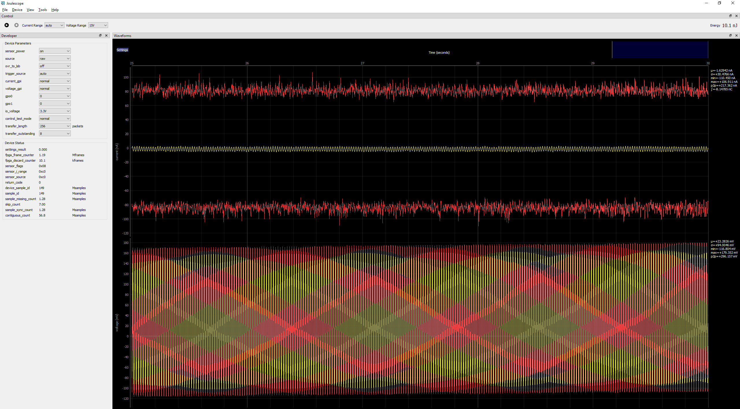
…with my DUT connected to “OUT”, in it’s sleep mode, it appears sensor range is set to 0x88.
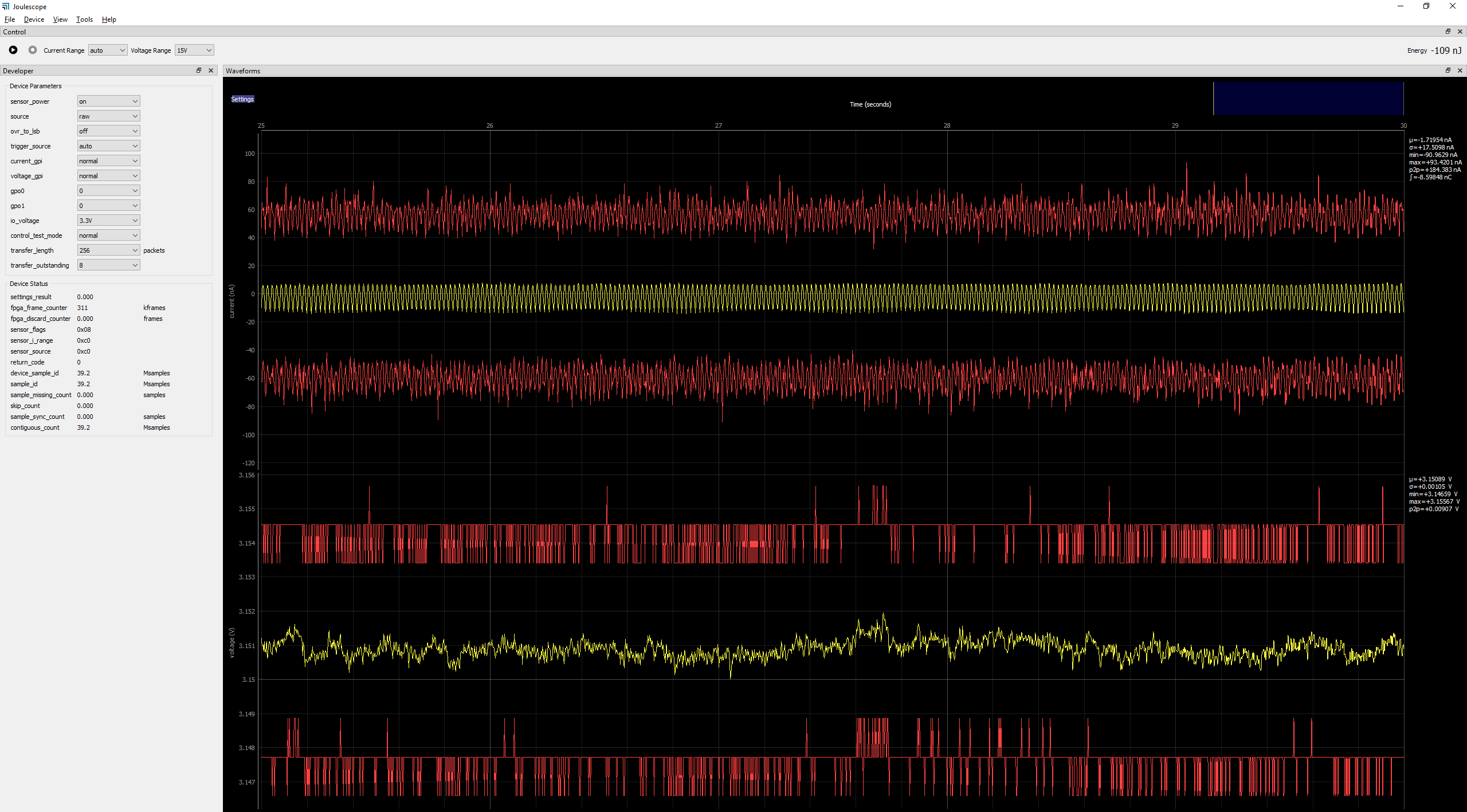
…switched to manual range of 18uA, you can see the reading in the stats at about 19uA, the graph range still shows mA though.
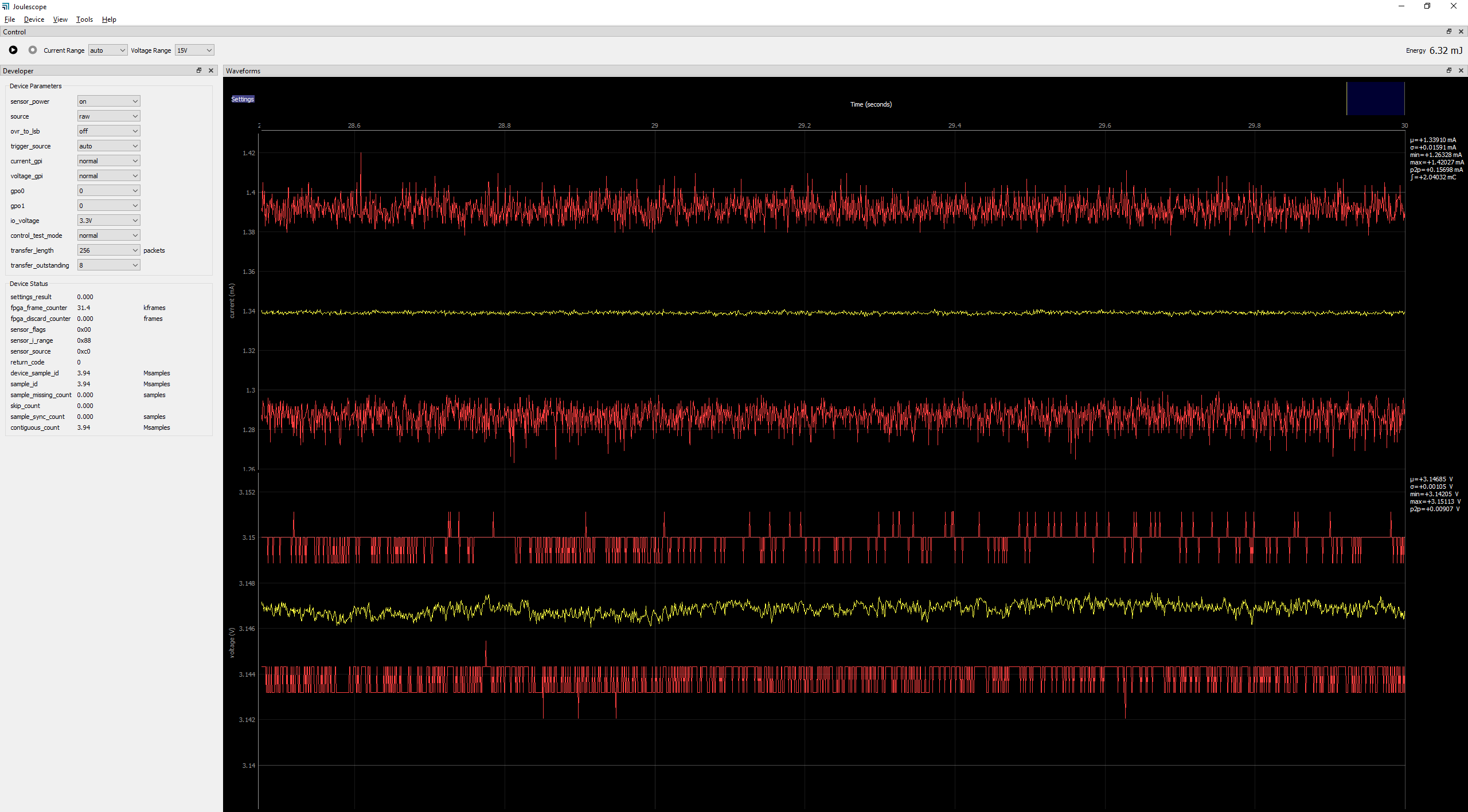
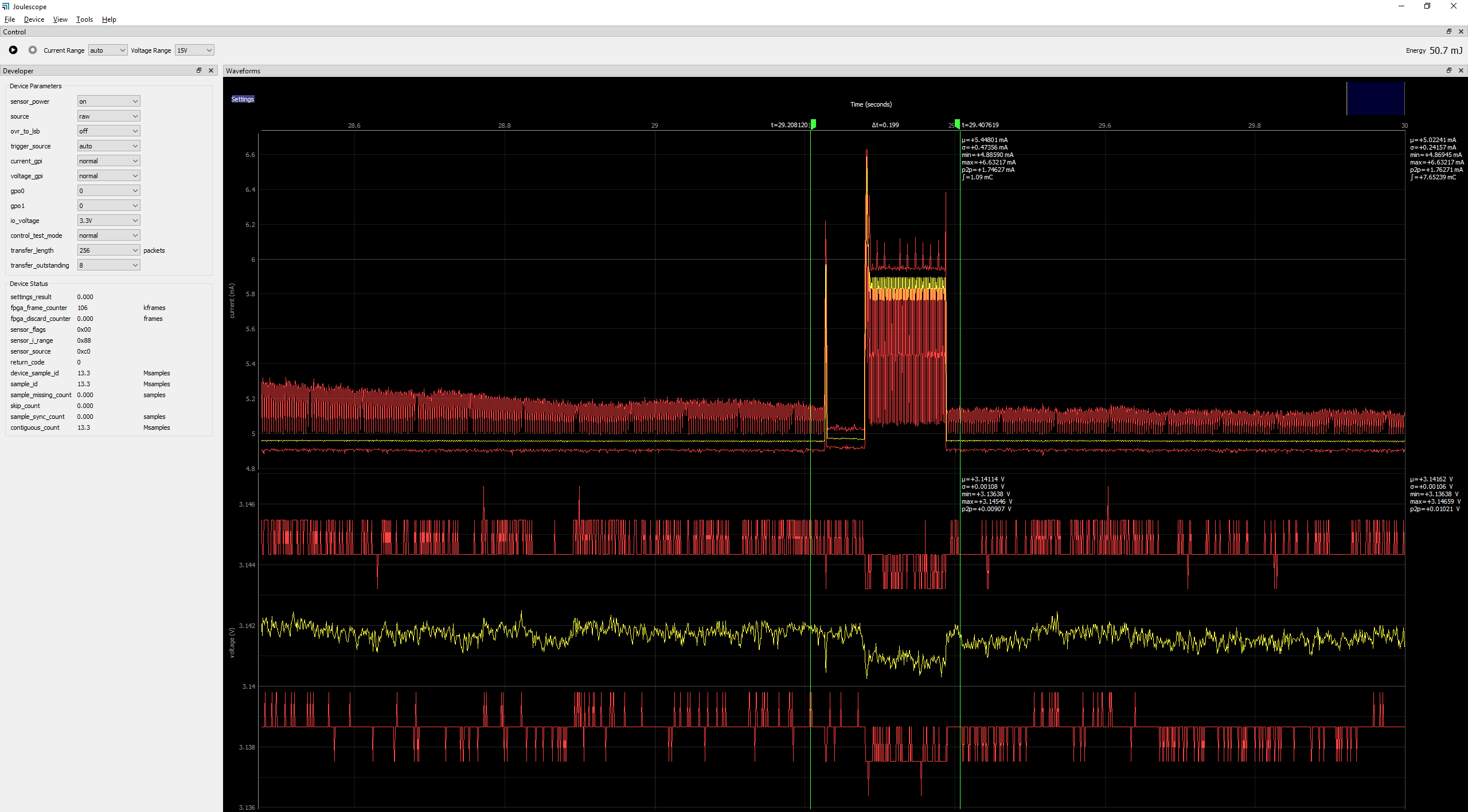
…the transmission capture, back in auto mode. File is attached for the dual marker area of this.
capture1.jls (1.4 KB)
Hope this helps.
Thanks.
Liam.
Hi @Ldr1970 and thanks for the information. Here is my feedback. The first two captures look as I would expect. Your Joulescope is correctly autoranging to the most sensitive 18 µA range with nothing connected. Your DUT appears to be drawing 1.34 mA in figure 3, and your Joulescope autoranged to the 18 mA range, which is fine. It probably could autorange down to the 1.8 mA range for improved resolution and lower noise. However, this is the defect that I hinted at earlier, but your Joulescope still makes correct measurements, just with worse resolution and noise than it could have.
On figure 4, we have a misunderstanding:
Your Joulescope is actually saturating at the maximum value for the range, which is why standard deviation (σ) is zero. If your device is still drawing 1.3 mA with Joulescope’s 1000 Ω shunt resistor in the 18 µA range, the voltage drop across Joulescope is 1.3 mA * 1000 = 1.3V, meaning your target only sees 3.14 V - 1.3V = 1.84V, which may make your target brown out.
The last figure looks like Joulescope is working correctly. Unfortunately, JLS capture files are currently truncated to increments of 0.2 seconds. Your capture has 0.199 seconds, which means the file has no data  I first noted this issue here.
I have a few requests:
- Could you try again to collect a capture between 0.2 seconds and 0.5 seconds long and then post the capture?
- Are you sure that your device is going into its lowest power 16 µA sleep mode? It’s probably worth double-checking using your previous test method while Joulescope is also connected.
Thank you!
Hi, thanks for looking at the issue.
I’m certain my device is sleeping at about 16uA, and in fact this is what the Joulescope was previously recording, the system setup didn’t change when it started reading 1.3mA.
We have many devices of this type in the field (easily more than 2000 of them) we generally get 2 years of battery life. If it were sleeping in the mA range this would not be the case.
The issue exists at the other extreme too, I really wish the radio only took 5mA! It’s minimum transmit power is almost twice this.
I will do some more tests later and also at work tomorrow with the exact same setup but a few different instances of the DUT.
I will try to include a trace with some data in, didn’t spot the file was empty.
Thanks again,
Liam.
Hi @Ldr1970 - My point was not to doubt that your design is achieving 16 µA or 5 mA in the field. My request (2) is to double check the current that this specific device connected through this specific Joulescope is actually drawing. The working assumption is that Joulescope is measuring incorrectly, but it’s worth a moment to double check that since your Joulescope seems to think that it is working correctly. I can think of a few potential issues, like your target board browning out, that could cause unusual measurements. If the total system is right on the edge, then changing cabling, even the location & geometry of the wires, can change impedance/inductance that could give different behaviors.
This brings up a few more questions:
3. What is the power supply input capacitance on your target board? I typically recommend >10 µF to give 3% @ 3.3V w/ 1A jump (see explanation in “Theory of operation” section of the Joulescope User’s Guide), but we can compute the expected voltage drop for different values.
4. What is the lowest supply voltage that your board can tolerate and work correctly?
Thanks, and I look forward to hearing what you find tomorrow.
Hi,
I will try a few different boards and wiring lash-ups to see if this makes a difference, I will also try it from my bench PSU rather than batteries.
I don’t think it’s a brown-out issue as the system continues to operate with the correct timings between transmissions and such like. I can tell when the system has been reset as we have a “fast transmission cycle” immediately after boot up before it settles down into a “mainly asleep” mode, this would be plainly visible on the power trace and I’m not seeing this.
The input capacitance of the board is quite low at about 10uF in total, we have no regulators or charge pumps on board. The micro will run down to 1.8v and I have seen voltage drops of about 300mV with previous measurements so with batteries at 3.1v we should have a good amount of headroom.
My only concern is that it was working fine showing me exactly what I expected to see and then it suddenly started behaving differently and no matter what I do I cannot appear to get back to the original measurements. Testing it on my office set-up will be the key here, if it works at the office as it did on Friday then we can put it down to something environmental in my home setup.
Will let you know. Thanks again for your attention to the matter.
Best regards,
Liam.
Hi @mliberty, Works perfectly on my work setup as it did on Friday…
So this is good news, the hardware appears to be running fine.
This is with the same lead setup, same cells, same software but with a different instance of the DUT. Although I did try 2 devices at home and they gave the same “apparently incorrect” results after previously giving the same results as shown here.
I guess this could be down to some external environmental issue or probing setup. To be fair to the Joulescope my leads are fairly long for such a fine measurement at the low range.
I wonder how easy it would be to add the “current range” to the annotation marker text? This might be a useful diagnostic in extreme range switching scenarios.
Thanks for your help and attention to this and sorry to have wasted your time.
Thanks,
Liam.
1 Like
Hi @Ldr1970, great to hear that your setup is working! I certainly don’t consider this a waste of time, and I still do not understand why the setup was not working at your home. Joulescope may not automatically downrange correctly in the presence of noise (it measures the noise, too!), but it should still uprange correctly. Seeing 5 mA instead of 150 mA is more likely an issue with the target device or the full system setup. One way to completely isolated Joulescope is to set it to the 10 A range.
You won’t measure the target device’s sleep current accurately in the 10A range, but you will certainly see 150 mA above the noise floor. If you want any help in finding the root cause, let me know!
Thanks for your suggestion to add “current range” to the annotation markers & noted! I also plan to add a current range signal for display in the waveform view when I add the GPO signals.
Thanks for taking the time to communicate this issue! If you have any further questions or other unexpected behavior, don’t hesitate to follow up or post a new topic.
Hi,
Just for completeness, the reason I wanted the Joulescope was to help determine why it uses 16uA in sleep mode when all the documentation suggests it can be as low as 1.21uA.
With the help of this wonderful tool I have now identified the register settings in the MCU that were causing the issue and have now achieved around 1.25uA in sleep mode, which is a low as I can expect from this MCU in the configuration we have.
Many thanks for a great product that makes our product better.
Best regards,
Liam.
3 Likes
@Ldr1970 @mliberty
That’s exactly what I was hoping to do with mine and it does it! I cannot tell you how accelerated my personal command of the new ATtiny 0 series chips has been thanks to this device in only a few days sitting on my desk.
@mliberty feel free to paraphrase my words and use in promotional material! Just watch out for the backlash when people find out what kind of clown you were quoting.
2 Likes