Possible autoranging with negative microamps issue (and note about imbalance)

I got my Joulescope set up today. I’m really happy about the painless install process. The first thing I tried was to test it on some current sources that I have (picoamp sources and electrometers configured as current source). I’ve found a potential issue (and a potentially useful note for the User’s Guide). I didn’t really dive deep into it but maybe you already know what’s going on.

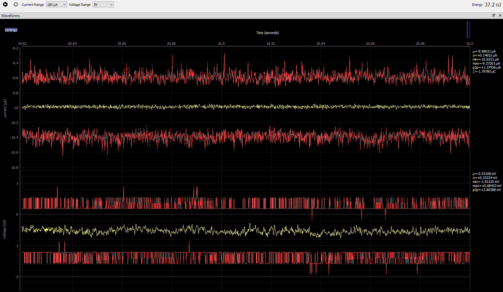
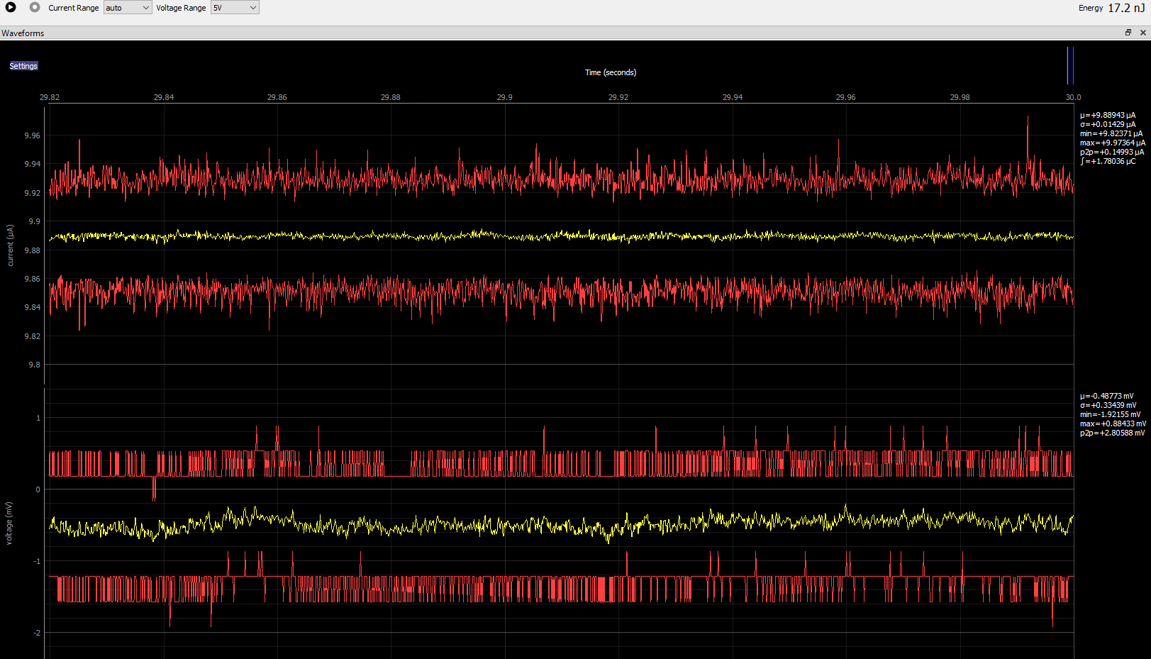
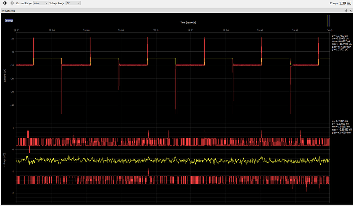
The issue: when sourcing microamps into the Joulescope (so the Joulescope reads negative), I find that between -5µA and -42µA (inclusive) I get a very nasty autoranging that also seems to be 60Hz-triggered. At -43µA I get a very clean looking signal. From -44µA to -100µA I get a waveform with spikes every ~8ms. I haven’t taken a look with an oscilloscope to see if there’s something happening at an even higher frequency that isn’t being picked up in the Joulescope waveform mode, though I’m not sure why it would only happen in one polarity. See Figures 1 & 2 below. It’s obviously changing ranges, the problem disappears with range=180µA.


Figure 1: -10µA source, OUT- grounded, range = auto


Figure 2: -10µA source, OUT- grounded, range = 180µA

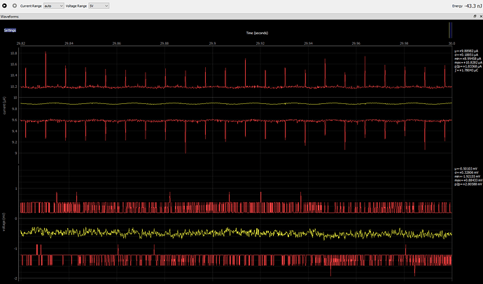
In Figure 3 you’ll notice that when I swap polarity, the autoranging stops and the measurement is spot on. I swapped polarity at the source, not by swapping the banana plugs (this is important because my source is chassis-referenced and the chassis is grounded).


Figure 3: +10µA sink, OUT- grounded, range = auto

Also, I think you may want to add a note in the User’s Guide about the imbalance between the positive and negative terminals and the effect that can have on ground-related interference. By swapping around the banana plugs, tying the positive side to chassis / ground, I see a dramatic difference in behavior. I will note that the autoranging behavior is the same when I swap the banana plug polarity (ie, when I source -10µA, I get weird autoranging, when I source +10µA I do not see the autoranging), which means it is not related to a difference of the + and - operation of the picoamp source.


Figure 4: +10µA sink, OUT+ grounded, range = auto

My test setup is not ideal but this was a quick test. I’m using a Keithley 261 picoamp source (I’ve also tried a Keithley 610C electrometer as the 10µA current source, it exhibits the same behavior). I have the IN+/IN- terminals shorted together. I tried plugging the IN into a power supply at various voltages from 0-5V but saw no change in behavior. I have the picoamp source plugged into the Joulescope’s OUT port through a some coax to a BNC-to-dual-banana adapter. Obviously my setup adds to the imbalance issue, but if the Joulescope were itself balanced then it shouldn’t matter, you’d have the same chassis/shield-coupled interference whether you plugged the shield into the negative or positive terminal.

Any thoughts about what’s going on with the -µA measurements?

Thanks,
Nick
2 Likes

Hi @NickLL,

Thanks for the detailed information! I received a similar report from one of the Joulescope beta users a while back. I was able to duplicate the issue, and it looks like you have as well. I believe that I know why this is happening, but I have not yet had time to thoroughly investigate.

Your Joulescope is intended as a single quadrant (+V, +I) device, but it does support some -V and -I for transients. Joulescope’s fast autoranging feature only works on +I overflow. -I overflow range switching is handled differently and is much slower. Here are the designed ranges (not the guaranteed specified range) for each range selection:

*** VOLTAGE ***
Select     Range    Range
             min      max
     0   -1.16 V   16.8 V
     1   -513 mV   5.04 V

*** CURRENT ***
Select     Range     Range
             min       max
     0   -1.80 A    10.4 A
     1   -470 mA    2.17 A
     2  -42.7 mA    197 mA
     3  -4.23 mA   19.5 mA
     4   -423 µA   1.95 mA
     5  -42.3 µA    195 µA
     6  -4.23 µA   19.5 µA

As an aside, one of the earlier Joulescope prototypes was fully bipolar with four quadrant operation. However, I decided to go to (mostly) single quadrant operation to save cost and double the effective performance.

That said, you should not be seeing an autoranging oscillation on the negative side. I have bumped up the priority for this investigation.

1 Like

I should have also mentioned that your Joulescope is electrically isolated. The IN and OUT terminals are essentially floating with respect to chassis ground. You can safely connect your grounded equipment however you would like to Joulescope.

For safety reasons, you should not exceed ±48V between USB ground and any of the IN or OUT signals. Joulescope is not certified for high voltage operation and only has a 1 mm clearance from chassis ground which is not sufficient for high voltage operation.

Thanks for the details about the negative ranges. I did notice, based on the User’s Guide, that the Joulescope targets single quadrant operation, but I also saw that it is rated for negative current so I figured that I would try it out.

It’s interesting, and probably telling, that my observation lines up exactly with the negative range you’ve described. I saw this behavior from -5µA to -42µA inclusive, and according to your range chart the range limits are -4.23µA and -42.3µA. -5µA and -42µA are the minimum and maximum whole numbers within that second range, and I was only counting in whole numbers, so this seems like an issue with the logic around that range. I hope that this helps you to narrow down the problem.

Perhaps we should split the grounding discussion out to another thread, but in a quick response to your point, I understand that it’s isolated and that I can plug in ground to either terminal, but it’s not balanced, so you’ll have different rejection at the different terminals (the difference between Figure 3 and Figure 4 in my original post). It’s not surprising, but I thought it might be worth noting in the User’s Guide so that users know to be careful.

1 Like

I think that I now understand what you are saying about the grounding issue. The Joulescope measurements for current and voltage are both referenced to IN+. IN- and OUT- are shorted through the front panel with mΩ resistance. In the Figure 3 case, IN+ is shorted to IN- which is shorted to OUT- which is ground, so IN+ is ground :smile:. In the Figure 4 case, IN+ is left floating and only connected through the Joulescope shunt resistor (1111 Ω in 18 µA range) and whatever circuitry is in your sink. You will pick up additional noise in this case. :frowning_face:

The choice of IN+ reference is optimized for the normal Joulescope use case. While the load impedance can vary dramatically, the source impedance of the power supply or battery is relatively constant. By referencing measurements to IN+, Joulescope can make more accurate, lower-noise measurements for low currents. In your Figure 4 case, you are referencing to OUT+. Any noise pickup into OUT- and between IN- and IN+ will show up in the Joulescope current measurements.

A shunt ammeter is typically referenced to one of the two terminals. I suppose that you could reference halfway between the shunt resistance, but that would be very unusual, cost more. Although it would result in consistent noise pickup, you also would not be able to take advantage of the typically lower IN+ to IN- impedance.

Does this explain what you are seeing? Any follow up questions?

The 0.5.0 software [download] contains a firmware update that fixes this current range oscillation. The problem is quite simple. The FPGA was not correctly checking the undercurrent threshold on the negative side. It would downrange even when it would have been out of range in the more sensitive range. After a lockout period, it would then uprange. After a lockout period, it would downrange, … and back and forth forever. To get this right required using the calibration information, which is on the device but was not previously being used by the device (just the host software). The sensor FPGA is now configured with + over-range, - over-range, + under-range and - under-range thresholds based up the calibration, and correctly performs the checks.

I am going to mark this issue as closed. If you see any issues with 0.5.0+, please post here or start a new topic!

1 Like

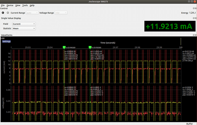
I’m not sure this is the same problem, but it may be.

While I would love to know that my device is drawing zero current, I don’t believe it. The left marker shows this, as well as zero volts. I am measuring processor current here. I believe 11.8mA (right marker) and 11.9mA (mean current meter). The frequency and duration of the gaps seem to correspond to when the processor is “asleep” (hard to verify that), but I would expect to see more current draw here (~ 5mA?) because of where I’m measuring.

Although a different, and much less important issue: V0.5 still leaves display artifacts on the screen. I can send a screenshot if you want.

-tim-

This may be important to check, considering the voltage is dropping to zero.

I’m measuring the current going in to the processor. While the processor current could go below 1ma during sleep, it’s also driving a couple of LEDs, some FETs and holding various pins “active”. These will draw current from the processor supply pin which I’m estimating to be ~5ma. All those loads will have to be mitigated separately, so I’m really interested in the difference between “Running” and “Sleep” modes of the processor. It’s also unlikely the voltage goes to 0V for 600uS. All kinds of things on the board will reset if that actually happens.

Hi @TimToombs, you may be seeing dropped samples. We have reports that running the Joulescope software inside VMs does not keep up with the USB 8 MB/s throughput due to the USB HW virtualization. When capturing live data, is the USB indicator at the bottom right green? It is red if more than 0.1% of samples get dropped, and yellow if between 1 sample and 0.1% are dropped.

1 Like

Just to update: You were correct, the USB indicator (which I totally missed) was red. After a native Ubuntu 18.04 install, this indicator is now green (Yay!) and all those funky dropouts seem to have disappeared. Thanks for the help!

1 Like