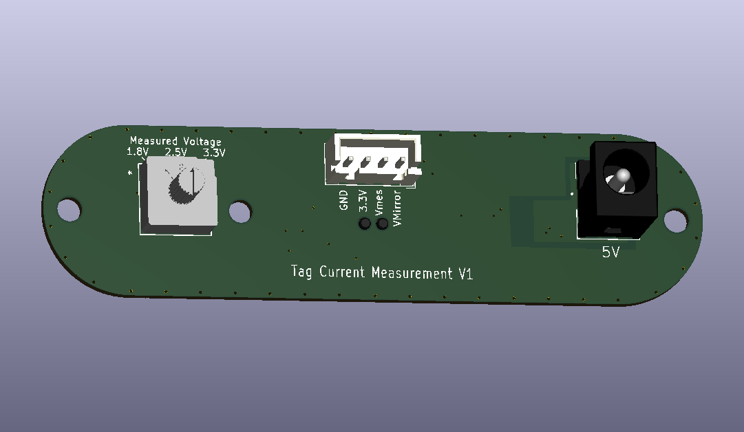
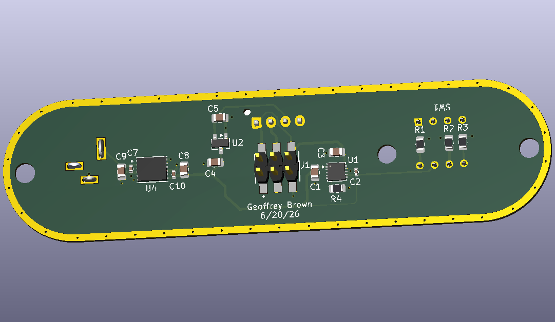
I have been using the stm power monitors for a number of years and have been increasingly frustrated by various issues. Consequently, I have ordered a js320. I do have a number of development boards created to support my research, so I wanted to emulate the interface which provides current measurement and a variable power supply. To this end, I’ve created a front panel (still to be fabricated) that provides three monitored voltages – 3.3v, 2.5v, and 1.8v (the 2.5v is because many of my research designs use small seiko batteries that are typically 2.5v). In addition, an unmonitored 3.3v output and a “mirror” of the monitored voltage is provided.
The design includes a UCC33420 dc/dc converter to isolate the 5v input from the usb ground and uses an lt3045 for the programmable voltage.
While I do a lot of extremely low-power designs, I don’t typically worry about low noise design. So I’d love feedback before I send to fab. I’m happy to send a link to the repo for anyone interested.
Hi @geoffrey - Welcome to the Joulescope forum, and thanks for making the leap to a Joulescope!
I need to do a design with the UCC33420. It looks like a very nice part!
I would be happy to review the front panel design. Please share the repo link, and feel free to DM me if you want to keep the repo private. I am @mliberty1 on GitHub.
A few general comments:
- If R1, R2, R3 are in the LDO feedback loop, the extra distance and impedance can cause LDO stability issues. C2 might already be this, but make sure you select a small cap in parallel near the LDO to improve the response from LDO output to the feedback input.
- If you care about nanoamps, think about PCB leakage currents. The Joulescope I+, I- and V+ are usually about the same potential (low leakage between them), but V- is usually offset by the full voltage. Try to keep clearance as far as possible, often the other side of the PCB. Also make sure you thoroughly wash the board after assembly. I have success with water-soluble flux, hot water, and a toothbrush.
Matt,
Here’s a link hardware/BoardDesigns/js320-faceplate at main · tag-designs/hardware · GitHub . It’s part of a large repo with software and hardware for my research activities. It’s all public
Schematic
The schematic looks good to me. I have opinions about unshown connections by name like sens… I also notice that C2 is 22 nF, while the quick example in the LT3045 datasheet shows 4.7 µF. I didn’t read the datasheet, but check that 22 nF is sufficient.
Layout
The most sensitive node for leakage is Vmeasure. Any current that leaks from Vmeasure to GND on this front panel is attributed to the target. The JS320/JS220 front panel does not include guard signals to make this easier. Leaking from Vprog to GND does not matter, so we can use Vprog as a guard signal.
I would remove the topside copper near pin J3.2. For extra insurance, you can route Vprog entirely around J3.2 on the topside as a guard trace.
Likewise, you can guard J1.3 by routing Vprog on a thin trace out of J1.1 and then between J1.3 and J1.5. J1.4 is already guarded by Vprog.
I would use filled zones to connect U4 pins and caps for VINP, GNDPWR, GND, and VIN. Whether the reduced impedance actually matters in practice, I don’t know, but UCC33420 section “8.4.2 Layout Example” shows this, too. On a two-layer board, you are not adding much high-frequency capacitive decoupling since the layers are separated by the full board thickness. This part uses 60 MHz switching, so I would add more GND via stitching and give GNDPWR a full path on the backside, too.
You should also follow the LT3045 “Figure 8. Recommended DFN Layout” from the datasheet. Note how the ground connections are all made on the component side, which means rotating C1 and pushing C3 left a bit so they can share the ground. It also shows filled zones to help reduce impedance. Note how the example shows U1.9 connecting separately to C3.1 rather than shorting U1.10 directly to U1.9. I also like to route enable separately so I can cut the trace if need. Doesn’t normally matter except in those rare cases where you get the polarity wrong!
Hope this helps, and let me know if you have questions!
Thanks ! I wasn’t sure if I should do a ground pour on the component side, your suggestion re ground stitching seems to point in that direction.
Geoffrey
Thanks, that was a huge help. Good catch on C2 – clearly operator error. Switched to 470nf which seems to be a compromise between minimum noise and startup time. I think I implemented most of your suggestions
Hi @geoffrey - Looking better!
For these type of fills, you normally want to remove thermal relief to create a simple, solid copper area. The caveat is you still want a relatively balanced thermal mass on 2-terminal parts (R, C) to prevent tombstoning during assembly, which is more important for production than a few prototypes.
Thanks! You learn something new every dang day!
After some delay in getting parts, I finally have my front panel up and running. Thanks for all the help. Nice to have a clean interface to my development boards