We are pleased to announce that the Joulescope JS110 front panel baseline printed circuit board design is now available for KiCad EDA. This new addition complements the existing front panel designs available for Autodesk Eagle.
A huge thank you to @simonmerrett who lead this effort and contributed his open-source design to the Joulescope community!
If you are a KiCad user interested in Joulescope front panels, we would really appreciate a separate set of eyes to review this design. Feel free to provide feedback however you are comfortable: comment on this topic, open new topic, or open an issue on GitHub. Thanks!
1 Like
@mliberty Do you know if anyone has used the Kicad files to make a custom front panel?
I was thinking of making one that would accept power input from a bench supply and have USB type-A for the output.
Sid
Hi @SidPrice - Sounds like a great idea! Are you planning on making it public? If so, I would be happy to pay your fab (OSHPark, PCBWay, JLCPCB, or similar) and component costs. DM me with the total, and I will send money via PayPal 
I don’t know if anyone has used the KiCAD files. I know that @simonmerrett started a front panel design based upon this, but I am not sure if it was ever successfully built. Hopefully, he can add let us know.
I know a number of people have made boards not based upon the “official” EAGLE or KiCAD models. I am not sure what Colin O’Flynn used, but it may have been KiCAD:
https://twitter.com/colinoflynn/status/1293620926731431939
You can contact him through Twitter or the Contextual Electronics Forum. If you would like, I can also ask him directly.
Hi @mliberty, yes it would be public and open for anyone to use.
Maybe readers here can express an opinion about the connector type for the PSU input.
No worries about the fab, it will be good to put something back into the community 
If anyone has a proven Kicad template it would be good to make use of it, or, the @simonmerrett project could be used.
1 Like
@SidPrice I still have the front panel for my power supply on my to-do list! So not verified yet.
Regarding the connector type, there were some suggestions in this poll thread I started, which may help your thinking. Poll: Custom front panel connections
I do have a run going into a fab before the weekend so if you want me to test a design before you order your own, I’d be happy to do so.
1 Like
Hi @simonmerrett, I have not designed the board yet, however thanks for the fab offer.
I think I am going to go with a terminal block for input and USB type-A for output.
I grabbed the GitHub repo for the base board but Kicad doesn’t like opening the schematic file, can’t find the symbol. Probably just a library configuration issue.
If you could share the board you worked on in the alternate thread you mentioned I would be interested in seeing that.
Sid, sorry but that file is on another PC and although I hoped to get on there to grab it for you, I haven’t managed yet. I will keep trying but there’s a lot of pressure on other tasks at the moment.
@SidPricefp_terminals.zip (233.6 KB) hope this gets you up and running. Sorry for the delay.
1 Like
Great, Kicad did a symbol update and then all looks good
@simonmerrett Spoke too soon. The footprint for the baseline components is not in the repository. Seems you have a footprint library called “SiCAD” that contains it.
@mliberty Working on the terminal input and USB Type A output front panel. I assume there is no reason I should not remove the lower two mounting holes, just like your USB front panel? Required so that the USB connector doesn’t overlap mounting holes.
Also, I need to extended the front and rear power zones to encompass the USB connector and to nicely position my terminal block.
Do both these changes to the “baseline” sound OK to you?
Yes, you can remove them. While nice for more mechanical rigidity, they are certainly not needed.
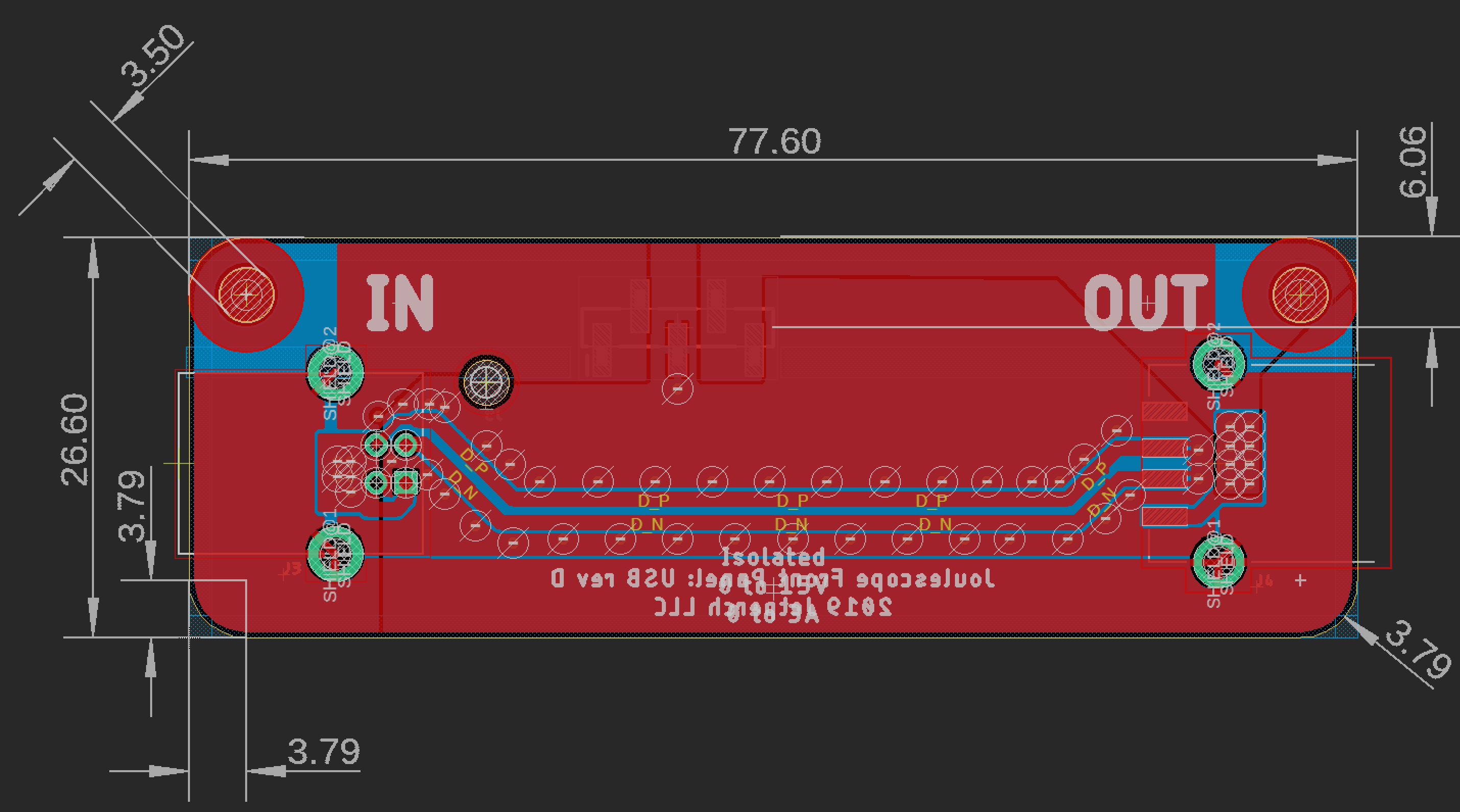
Go for it. They are pulled back from the enclosure to help reduce noise pickup. You do want to keep them from making contact through the screws, though. For reference, here is the USB front panel which has the planes extended:
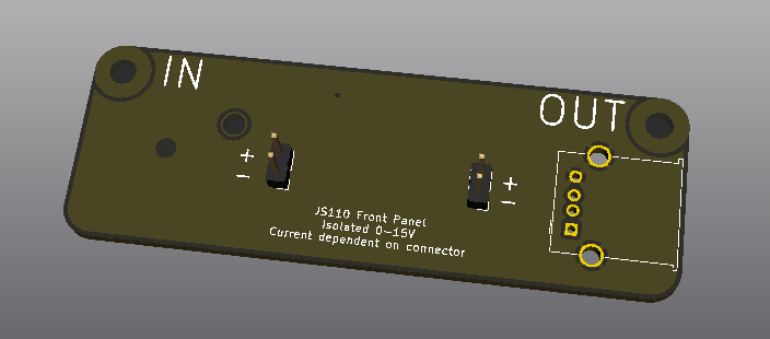
@mliberty The following suits my immediate application to connect a bench supply to either a header or USB Type-A.
Will probably order some from OSHPark in a little while.
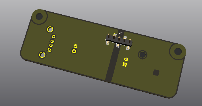
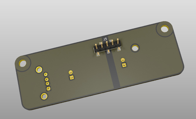
Cool. In the rear render, the left pin 1 is not connected to the back plane. On the right, it looks like both pin 1 and 2 are connected, which seems odd. Otherwise, looks good!
Looks like I forgot to refresh the zone fill before I snipped the renders:
Thanks.
1 Like
@mliberty @simonmerrett OSH Park has just shipped my boards. Unfortunately, it seems I forgot to order the USB connector, so a longer wait to try it 
Sid
@mliberty Should be assembling a panel this week, the USB connector package got lost in the mail
Do you have a part number/source for the light-pipe?
The light pipe is the Dialight 51513020125F, available from both Mouser and Digi-Key. The Samtech connector is the TSM-105-01-S-SV. The drawing has the part number and locations:
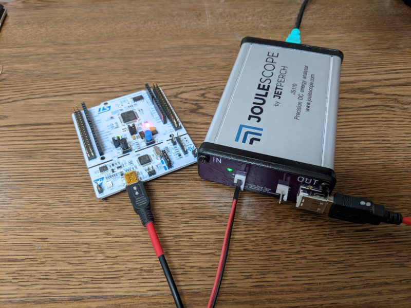
@mliberty, @simonmerrett I have my front panel assembled and working. It allows me to use my bench power supply for safe powerup of PCBs and JS monitoring. I imagine I will mostly use the supply output rather than the USB output, however, having the USB is a useful feature.
It is available on OSHPark if anyone wants to build one.
OSH Park ~
2 Likes
Looks great @SidPrice! I have a couple of quick questions:
-
Do you have a part number for that locking header connector you used?
-
Does the locking feature also make it polarized?