I’ve seen a few other posts of higher than expected current when autoranging, but have not seen the question of higher currents in a fixed range answered.
I am measuring a BLE device that I would expect to have maximum currents of around 3mA. So, I set the Joulescope to measure in the 18mA range and I’m seeing peak currents of ~12mA. I do not see the device saturating. I am using an external power supply and very short wires to and from my device. My input capacitance should be around 10uF (with derating applied). Could you explain why I might be seeing such different maximums than expected? Thank you for your help!
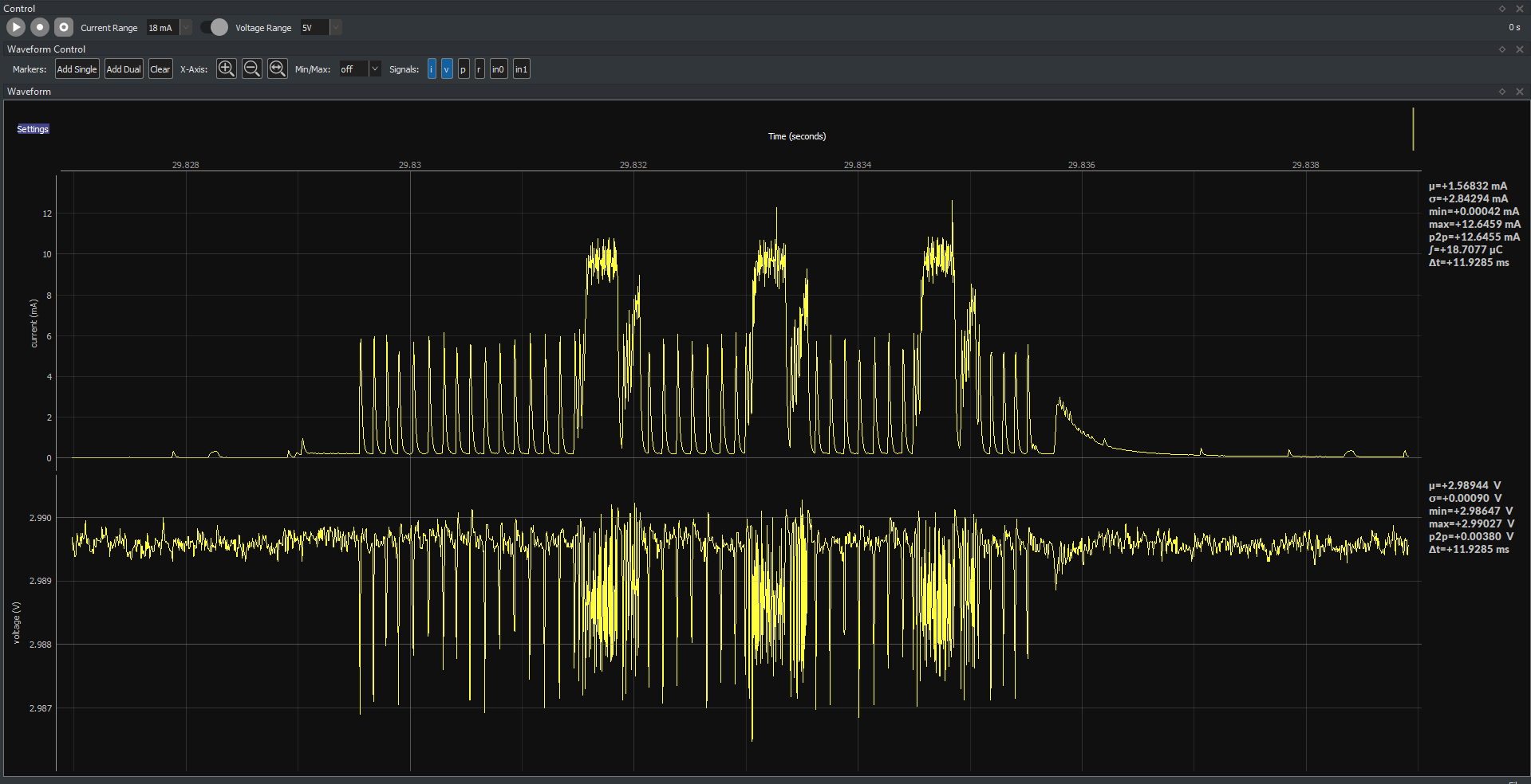
First question: why do you think your device has a maximum current of 3 mA? The “maximum” current depends upon measurement bandwidth. If I look at the plot, I estimate an average current of about 3 mA during that activity window (1.5 mA over the entire plot with roughly half being the activity window). If you were to look at this same activity with a 1 kHz sampling rate, which you can do using downsampling, you won’t see this peaking as much.
Now, we have had some infrequent reports of RF energy coupling into the JS110, either conducted or radiated. However, these have been with much higher power radios, like +30 dBm that were poorly located. In one case, the wires connecting the device to the Joulescope were accidentally part of the antenna. In another case, the JS110 enclosure became part of the antenna. The Joulescope JS110 measurement range is asymmetric, and it measures more positive than negative. Extreme RF signals get rectified resulting in a DC bias.
You can do a simple test to see if this is the case. First, locate the device further away from the JS110 by using longer wires, say 2 feet. Ensure that you twist the OUT+ and OUT- wires together to minimize the loop area and RF pickup. Do you measure the same values? If so, the Joulescope measurements are likely correct.
The next step to build confidence is to use another piece of equipment to confirm the measurements. Do you have access to an oscilloscope? Oscilloscopes are usually earth-ground referenced, which can complicate things. Assuming you can float your system or the oscilloscope, you can measure the voltage across your Joulescope’s IN+ to OUT+. You will expect to see about 15 mV (12 mA * (1.11 + 0.015) Ω). If you can disconnect your target device from everything and power using a battery, then you don’t need to worry. If you need help otherwise, let me know!
I believe I was misunderstanding the spec in the datasheet. It says the BLE operating current during Active Tx should be 3mA typical. I expected that this would mean the maximum change from baseline would be 3mA, but now that I’m looking more closely at those three BLE transmit peaks they are approximately 3mA above the higher frequency peaks- so perhaps there is a superposition happening with the power to run the core and the specific BLE power required.
In the interest of responding to your suggestions however, I did try longer twisted wires on the output and did not see a change. I agree the low power bluetooth antenna (0 dBm) is pretty unlikely to couple into the wires.
Good idea to measure the voltage across the sense resistor as a way to verify. I am measuring 34mV maximum when seeing it get pretty close to maxing out at 20mA on the Joulescope. I’m operating with a coin cell when using the scope though, so I believe my source resistance is much higher than your estimate of 0.015ohms.
So- user error on my part. Sometimes talking through an issue makes you realize where the problem lies.