Hi @Ivanovitch_k
Joulescope is a shunt ammeter, which means that it places a resistor in series with your target load. The total source resistance as seen by the load consists of:
- The Joulescope shunt resistor
- Other Joulescope resistances (traces, connectors, MOSFET)
- Wire resistance between Joulescope and the target
- Wire resistance between Joulescope and the source
- Internal source resistance
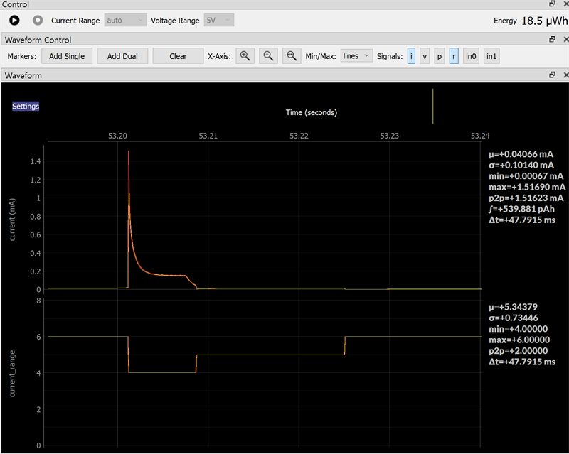
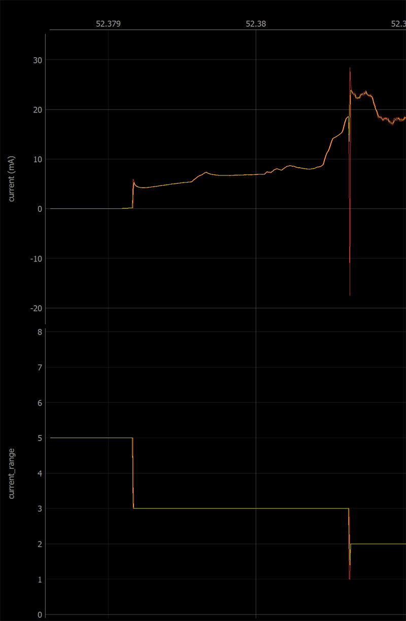
Let’s call this R. To make things more interesting, Joulescope’s shunt resistor value can change, as you have shown in the first image, which changes the total source resistance value.
Your target has capacitance C, typically from bypass capacitors.
The combination of R and C form a low-pass filter:
f = 1 / (2 π R C)
τ = R C
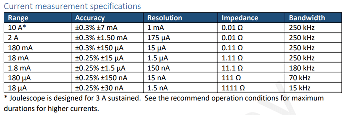
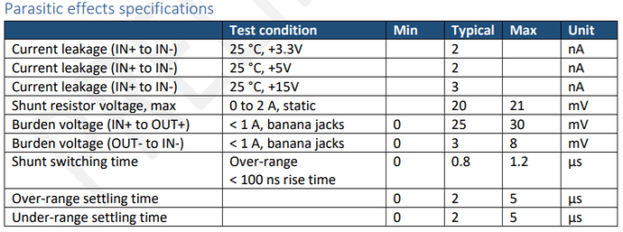
This filter can limit the system bandwidth to less than Joulescope’s measurement bandwidth, especially for low currents. The Joulescope User’s Guide contains details, including shunt resistance, for each current range:
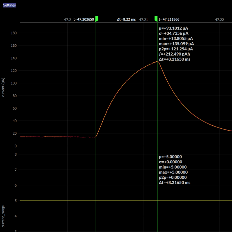
Joulescope’s 180 µA range uses a 111 Ω resistor. With 35 µF target capacitance, we expect:
f = 1 / (2 π R C) = 1 / ( 2 π 111 35e-6) = 41 Hz
τ = R C = 111 * 35e-6 = 3.9 ms
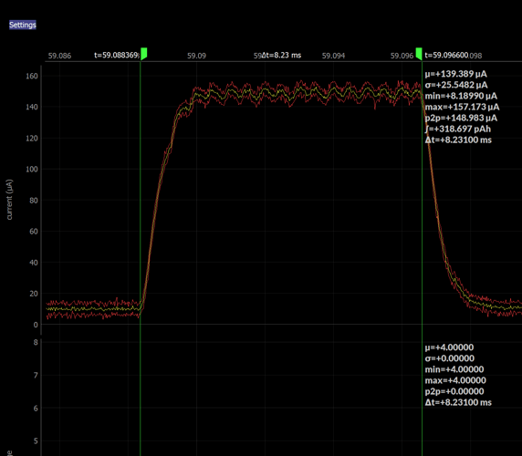
The time constant τ is the amount of time it takes to reach 63.2% of the final value. Looking at your second plot and attempting to project the final value, 3.9 ms seems about right. So, the second plot is what we would expect. The third plot looks good with the lower value shunt resistor and increased system bandwidth.
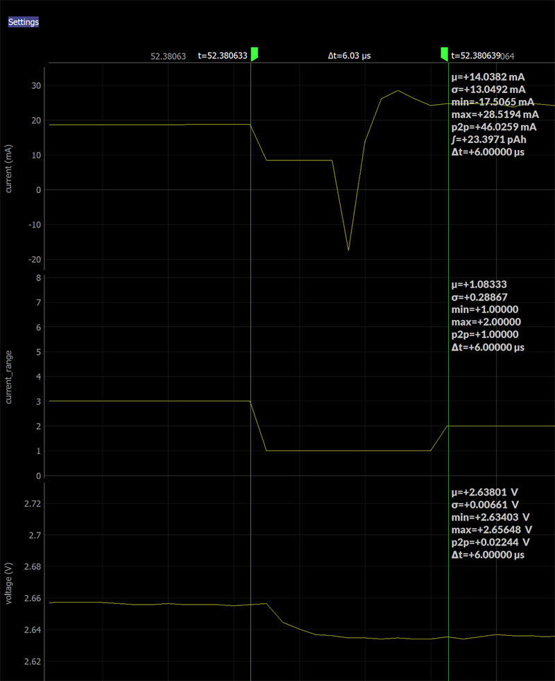
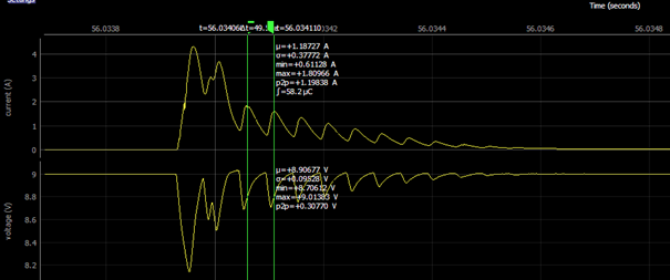
So, what’s up with that first plot? Well, Joulescope’s autoranging kicks in (as it should) and switches from 1111 Ω to 11.1 Ω then to 111 Ω, then 1111 Ω. The spike occurs on the switch from 1111 Ω to 11.1 Ω, but why? At this point in time, your target system increased its current consumption. This results in a voltage drop across the Joulescope shunt resistor, which is how Joulescope measures current. When that voltage drop reaches 20 mV, your Joulescope makes the decision to switch to 11.1 Ω. At this point, the voltage drop across Joulescope instantaneously decreases. The target capacitance needs to charge back up approximately 20 mV - 11.1 Ω * 150 µA = 18.3 mV at a rate limited by the new time constant:
τ = R C = 11.1 * 35e-6 = 390 µs
This explains the spike and RC time constant around 53.201 s in the first plot.
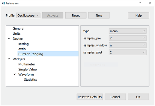
To get the “best” waveform, which most closely approximates your target load minimizing the effects of the target load capacitance and shunt resistance changes, manually choose the Joulescope current range which is greater than all expected currents drawn by your target system. The downside is reduced accuracy and significantly reduced dynamic range. If your target has lots of bypass capacitance, you can consider removing bypass capacitance for this test, or using Joulescope to measure just the current of a subsystem.
Note that Joulescopes do not presently have the ability to manually limit the current ranges used by autoranging. However, this feature may be added in the future.
A key point is that even when the system bandwidth distorts the current curve from what your sensor is drawing at the time, your Joulescope is measuring real current, and the total will still be correct. The waveform and RC time constants are correct, just not intuitive.
Does this make sense? Does it answer all of your questions?
