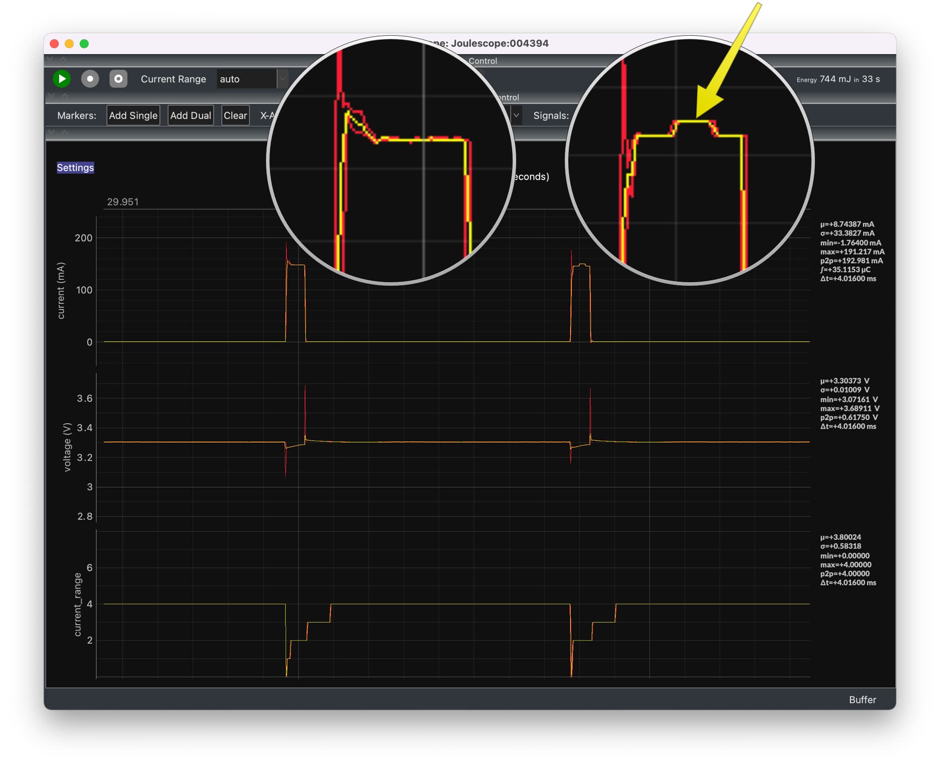
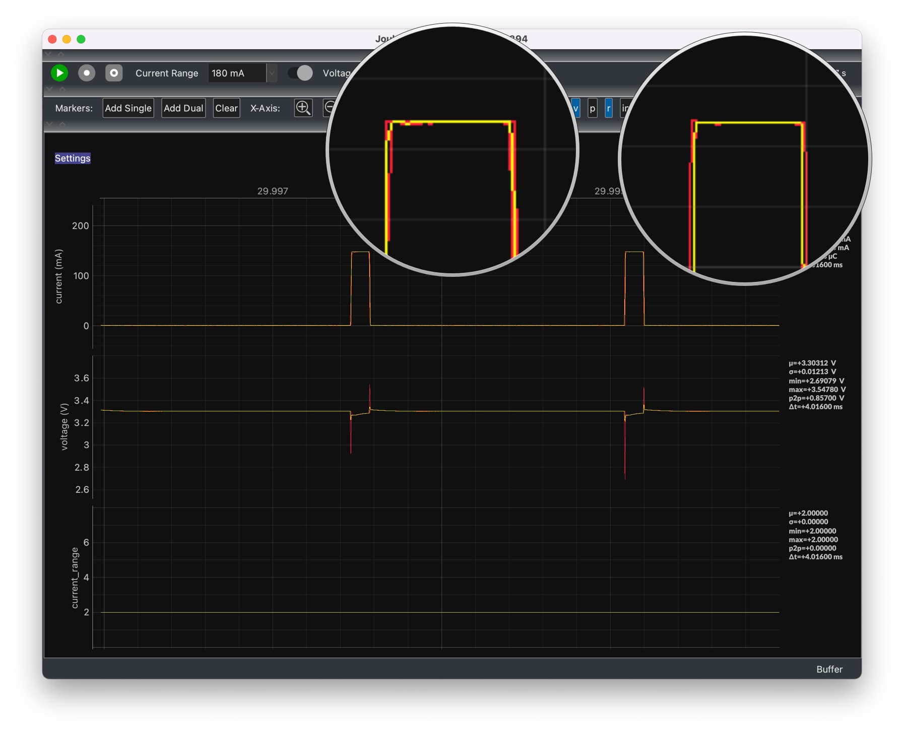
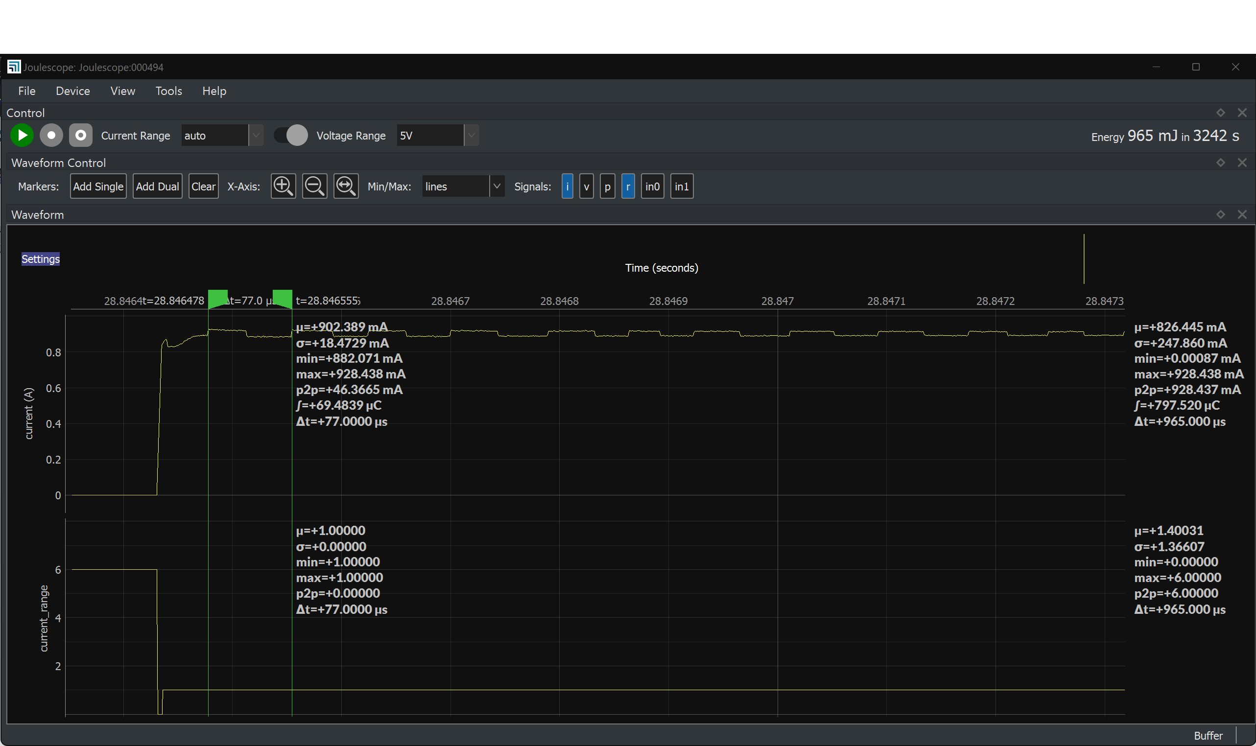
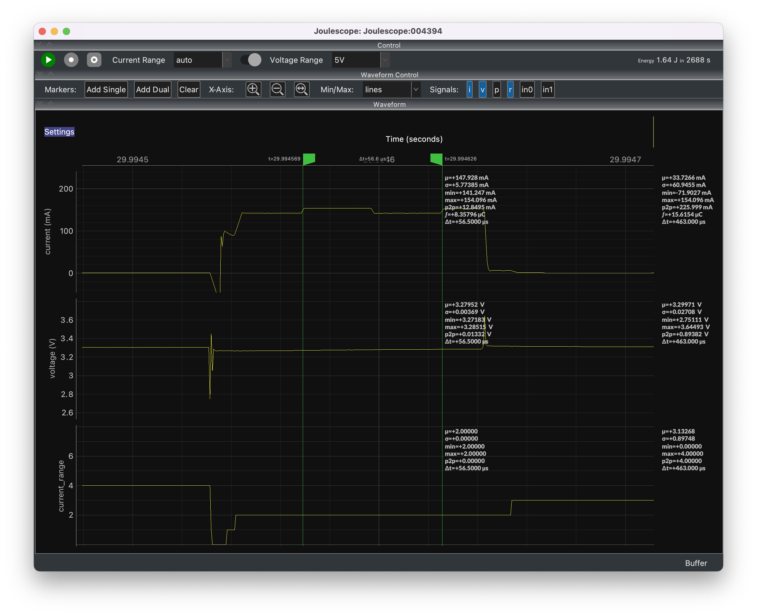
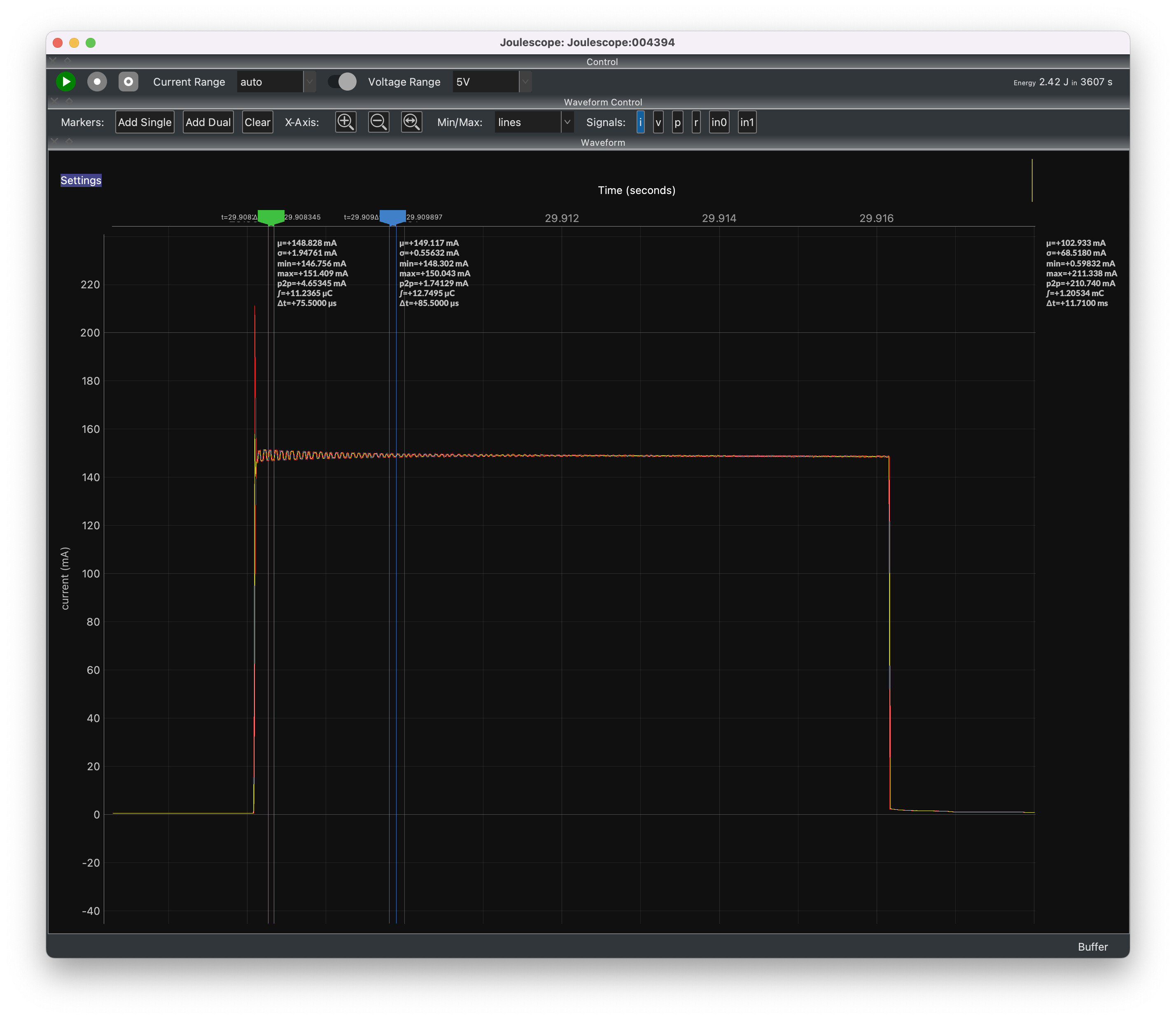
I have a pulse load circuit which periodically switches from high impedance to a 22 Ω load for 110 µs. If I manually set the current range, you see nice even pulses, but if you set the current range to auto, sometimes you see odd small step changes in current that are not correlated with current range switching.
Attached is a picture of what I see, highlighting the odd artifact. (If you look closely, the artifact isn’t aligned with current range switching.)
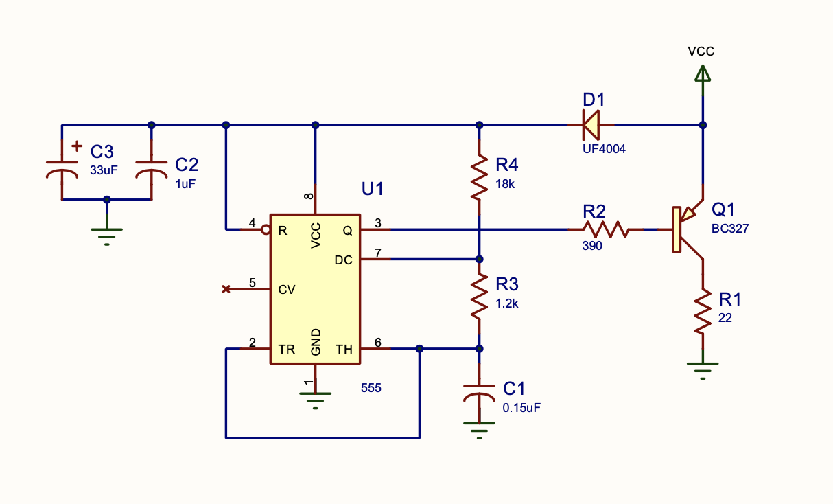
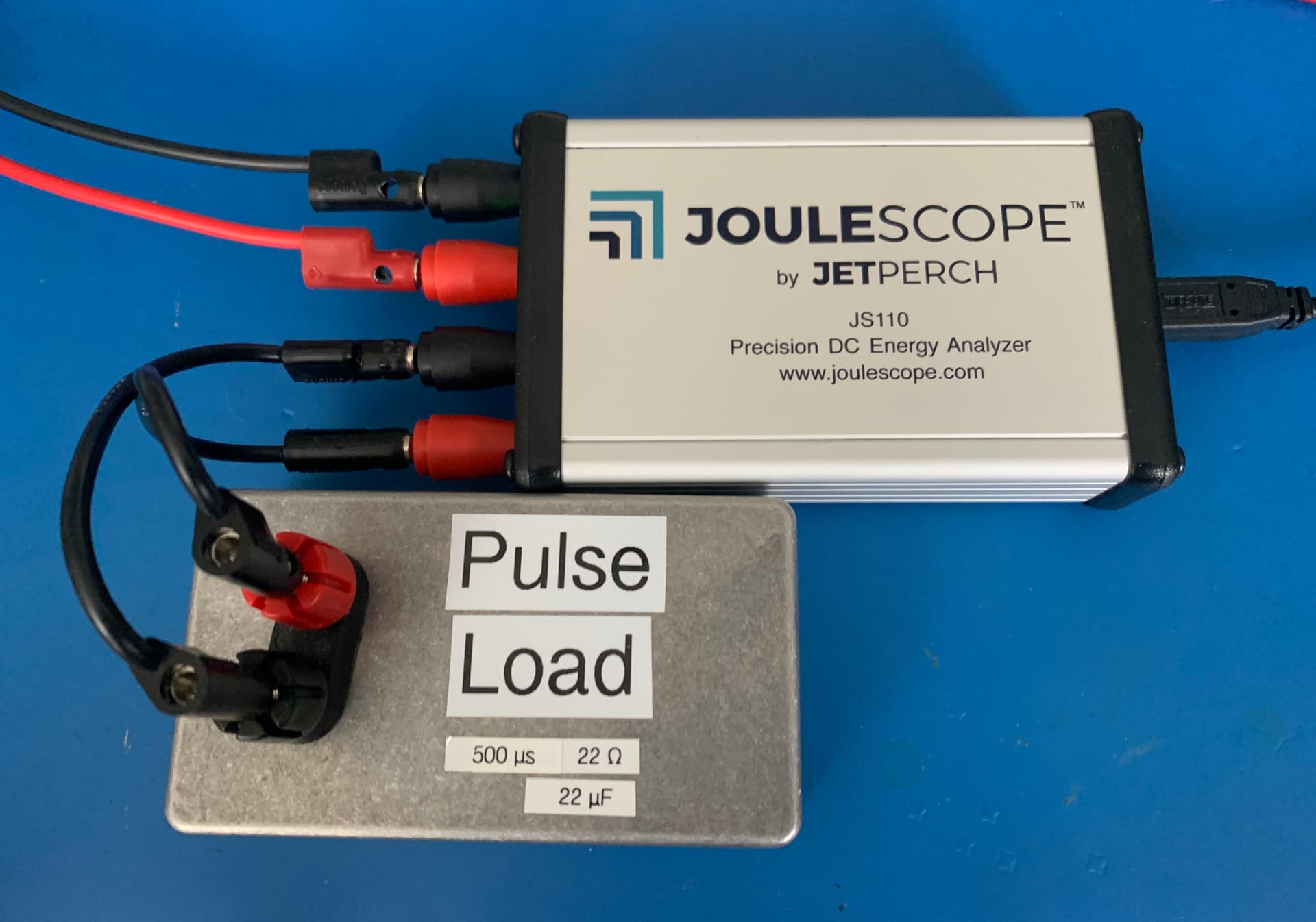
For reference, here is the pulse load circuit I am driving. The gist is that Q1 alternates between off and on, allowing current to flow through 22 Ω R1. D1 is there to simply prevent current from flowing out of the 555 subcircuit.
Hi @mfikes - That is a great, simple test circuit. Thank you for sharing the great screen captures and test circuit schematic. That 555 test circuit likely has rise times measured in 10s of nanoseconds, which is pretty unfriendly, too
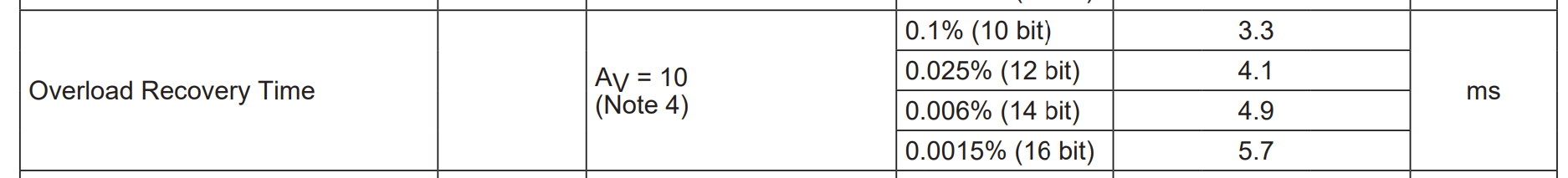
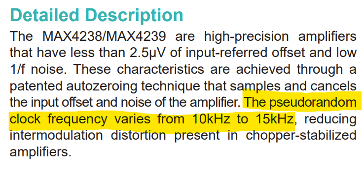
I suspect that this fast transient is causing the JS110 analog front-end opamp to misbehave. The JS110 uses the MAX4239, which is a chopper opamp. It definitely does not like being driven into overload. From page 4 of the datasheet:
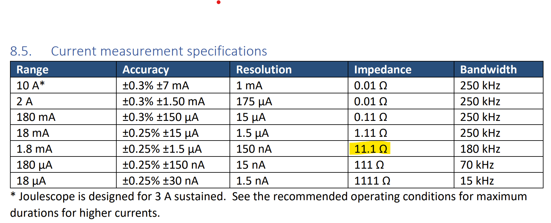
In the screen captures, your Joulescope was in current_range 4, which uses a 11.1 Ω shunt resistor. From section 8.5 on page 12 of the Joulescope User’s Guide:
With your circuit, 3.3 V / 22 Ω = 0.15 A. Your Joulescope sees 11.1 Ω * 0.15 = 1.6V. The opamp has a gain of 11 and saturates around 0.31 V, which is only 28 mA, so this circuit is definitely driving the MAX4239 into overload. While recovering from overload, the MAX4239 typically oscillates with alternating pulses between 10 kHz and 15 kHz, which is the chopper amp frequency.
Do you want to test my hypothesis that the MAX4239 is misbehaving? If so, you can modify your circuit to extend the pulse duration. I would expect that you will see alternating + & - ringing at the chopper amp frequency, with pulses somewhere between 66 and 100 µs. You can add dual markers to measure the duration.
We normally recommend that the target contain at least 10 µF of capacitance to reduce the system bandwidth and slow down those fast edges. In your test circuit, you would place this capacitance in parallel with the 22 Ω resistor R1 and Q1. This forms a RC filter. The R is actually the supply resistance and the JS110 shunt resistance. This slows the rate at which VCC drops when Q1 switches on. You can compute the time to saturation using I(t) = Imax * (1 - e ^ (t / τ)) [Wikipedia]. So t = τ ln (1 - I(t) / Imax) = 11.1 * 10e-6 * ln(1 - 0.028/0.15) = 23 µs, which is plenty of time for the JS110 to react and switch to current range 0.
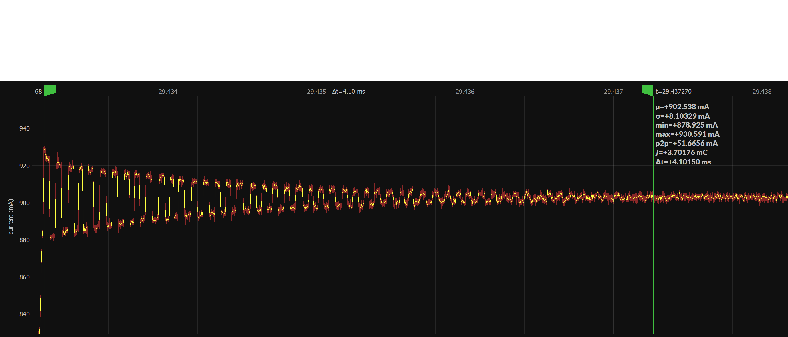
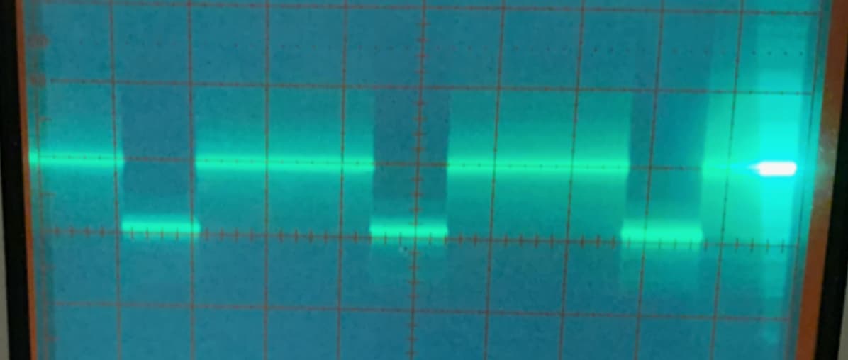
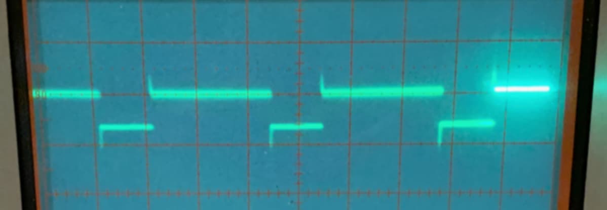
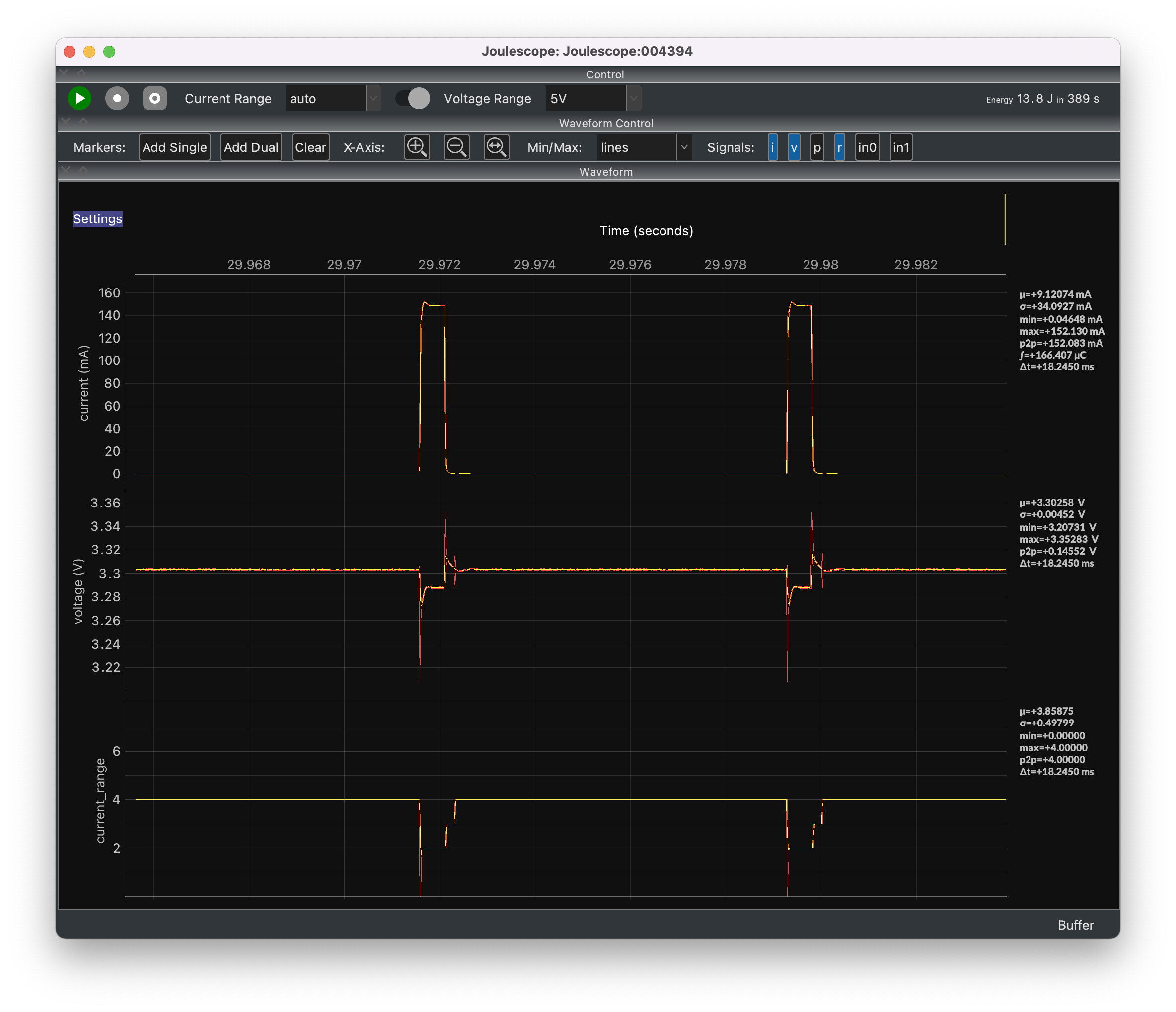
I revived an old test setup that uses an N-channel MOSFET and 1 Ω load. It is driven manually with a switch debouncer. I powered it using a bench supply. It took me a while to find a “winning” combination for oscillation, but I ended up with 1V with 2A limit. Here is what I observed:
So, this uneven pulse train is very characteristic of the MAX4239 overload. I expect you will see something similar if you extend the 555’s pulse on time.
Ahh, yes, the frequency lines up with that explanation (see attached screenshot, where you can see at least one cycle at 17.7 kHz). I’ll make a modified version of the circuit with longer pulse widths to see if the chopper effect fades away, and I’ll also play around with reducing the rise times. Now that you mentioned it, I’ve noticed that the chopping effect seems to appear in clumps, so maybe it spans several pulses when it occurs.
Your explanation is great—this is essentially what I was looking for: Deeper insight into how the Joulescope works in order to better understand it and its boundaries, etc.
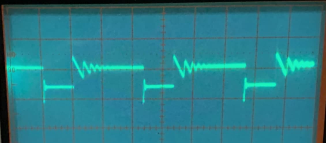
I built this circuit to test a Keithley 2306’s ability to measure current pulses, with the circuit roughly imitating the temporary 160 mA current draw associated with a Qorvo UWB chip when its radio is on, its effects when battery ESR comes into play, etc., and how well that PSU regulates (from that era, the 2306 was evidently deemed to be fast at regulating transient loads). It is a harsh circuit exposing the power supply directly to loading without bulk or bypass capacitors. For example, here is the effect of this circuit on the 2306’s voltage (you can see noise, as the 2306 appears to involve high-bandwidth switching to regulate):
Suffiice it to say, having a Joulescope to look at all of this certainly provides new insight, especially with the ability to directly see the current.
That test circuit will stress power supplies! If you want more detail about the JS110, the “Theory of Operation” section 10, page 21 in the Joulescope User’s Guide is a good place to start, but I think you are already beyond that. I think that the most public details show up in our recently issued patent:
Although it doesn’t help you now, the upcoming, next-generation Joulescope JS220 behaves much better on saturation. It uses the TI OPA2388 for the front-end opamp which has a typical overload recovery time of just 10 µs.
I have nothing to contribute to this topic, other than to say that you are amazing, Matt! I hope the people who own Joulescopes fully appreciate your involvement, enthusiasm, intellectual curiosity, and effort in providing the answers to questions that users pose, some of which would stymie many engineers. You are a modern day Jim Williams.
Great! I also re-read my post, and I noticed that I was not clear about where to place the capacitor. It has to go across both Q1 and R1, not just R1. If you place the capacitor across just R1, it actually makes the current draw worse since the circuit would need to charge up the capacitor, too. You want the capacitor already charged to help with the R1 current draw when Q1 turns on.