Autoranging questions

Hi there,

I have a system in which a sensor performs a periodic measurement, from a base current of around 10 uA to 130 uA for 7-8ms.

When I let the Joulescope autorange, It see the sensor spiking at almost 2mA ! This seems impossible as the datasheet of the sensor says a max of 130 uA.

If I switch to the fixed 180 uA range, the current values seems to match the expected but I get this sawtooth waveform:

snap, as new user it seems i’m limited to post 1 image per post…

Reading the posts around leads me to believe my system is severly bandwidth-limited in this range.
I measured 35uF using a DMM & DUT off (not sure if it’s the right way to do it though…).

Using the less bw-constrained range of 1.8 mA gives me this more plausible & close to reality waveform:

I tried to adjust the autoranging filter settings, but I couldn’t reproduce this good waveform. Is there something, like a combination of settings I could try ?

I have another issue, but I’ll wait the raise on image per post as to not spam too much :sweat_smile:

Hi @Ivanovitch_k

Joulescope is a shunt ammeter, which means that it places a resistor in series with your target load. The total source resistance as seen by the load consists of:

  • The Joulescope shunt resistor
  • Other Joulescope resistances (traces, connectors, MOSFET)
  • Wire resistance between Joulescope and the target
  • Wire resistance between Joulescope and the source
  • Internal source resistance

Let’s call this R. To make things more interesting, Joulescope’s shunt resistor value can change, as you have shown in the first image, which changes the total source resistance value.

Your target has capacitance C, typically from bypass capacitors.

The combination of R and C form a low-pass filter:

f = 1 / (2 π R C)
τ = R C

This filter can limit the system bandwidth to less than Joulescope’s measurement bandwidth, especially for low currents. The Joulescope User’s Guide contains details, including shunt resistance, for each current range:

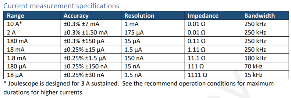
Joulescope’s 180 µA range uses a 111 Ω resistor. With 35 µF target capacitance, we expect:

f = 1 / (2 π R C) = 1 / ( 2 π 111 35e-6) = 41 Hz
τ = R C = 111 * 35e-6 = 3.9 ms

The time constant τ is the amount of time it takes to reach 63.2% of the final value. Looking at your second plot and attempting to project the final value, 3.9 ms seems about right. So, the second plot is what we would expect. The third plot looks good with the lower value shunt resistor and increased system bandwidth.

So, what’s up with that first plot? Well, Joulescope’s autoranging kicks in (as it should) and switches from 1111 Ω to 11.1 Ω then to 111 Ω, then 1111 Ω. The spike occurs on the switch from 1111 Ω to 11.1 Ω, but why? At this point in time, your target system increased its current consumption. This results in a voltage drop across the Joulescope shunt resistor, which is how Joulescope measures current. When that voltage drop reaches 20 mV, your Joulescope makes the decision to switch to 11.1 Ω. At this point, the voltage drop across Joulescope instantaneously decreases. The target capacitance needs to charge back up approximately 20 mV - 11.1 Ω * 150 µA = 18.3 mV at a rate limited by the new time constant:

τ = R C = 11.1 * 35e-6 = 390 µs

This explains the spike and RC time constant around 53.201 s in the first plot.

To get the “best” waveform, which most closely approximates your target load minimizing the effects of the target load capacitance and shunt resistance changes, manually choose the Joulescope current range which is greater than all expected currents drawn by your target system. The downside is reduced accuracy and significantly reduced dynamic range. If your target has lots of bypass capacitance, you can consider removing bypass capacitance for this test, or using Joulescope to measure just the current of a subsystem.

Note that Joulescopes do not presently have the ability to manually limit the current ranges used by autoranging. However, this feature may be added in the future.

A key point is that even when the system bandwidth distorts the current curve from what your sensor is drawing at the time, your Joulescope is measuring real current, and the total will still be correct. The waveform and RC time constants are correct, just not intuitive.

Does this make sense? Does it answer all of your questions?

Hi,

it does makes a ton of sense ! Thanks for the detailled info & maths behind. Revives old memories !
That option to clamp the autoranging would be great !

I had another issue with intermittent negative current spikes, but I can suppress them using the 180 mA range.

Not sure why the spikes go in the negative though, HW suspects the bypass capacitors release their energy all at once to absorb the current spike ?

closeup on the spike, it happens at range switch too:

On this one I observe a strange behavior, it happens more frequently if I power the DUT from a bench PSU rather than from a battery.

1 Like

Without more detail, it is hard to say for certain where these spikes originate. Power supplies are definitely active components which have step responses.

However, Joulescope does introduce some effects on current range switches. In addition to the RC filtering & time constant behavior discussed above, Joulescope also uses MOSFETs to switch the shunt resistors. All MOSFETs act as capacitors between the gate and source-drain. When your Joulescope switches ranges, it charges up one gate and discharges another gate. This injects net charge into the source-drain path which then disturbs the actual current measurement. The Joulescope software contains filtering for this:

I recommend the default settings. However, you can disable it to see what the software filters, and change it to best match your application. If you know your system bandwidth is already limited, you can apply a much longer filter. Joulescope autoranges on too much current in less than 1.2 µs, but it can take up to 5 µs to fully settle.

Thanks again for the detailled inner workings of the JS !

I played with the settings and found the spikes are gone if I set either window or post to a value > 6
And it doesn’t seem to affect the rest of the waveform, so that’s great !

I also saw the NaN type setting, may I ask what it does or when it might be useful ? It seems similar to mean…

I have to say I find this a bit worrying. Essentially it means that in any real system, a current step large enough to trigger autoranging will cause a spike that is not “real”, as it is caused by switching the sense resistors (charging the bypass capacitors). Can I trust JS with current spikes?

Hi @Martin

Thanks for the question. First, know that Joulescope has been tested extensively on real-world systems. In addition to the testing and development effort, numerous companies have now verified Joulescope performance independently. The only public announcement, as far as I know, is the work by EEMBC and Dialog Semiconductor on their upcoming Wi-Fi benchmark (see their newsletter). All testing has shown that Joulescope compares favorably with equipment that costs over 10 times as much as Joulescope.

Now, why? In addition to static accuracy and measurement bandwidth (which is common to all test instruments), Joulescope also has autoranging. I have yet to see any autoranging equipment that does not have artifacts on range switching. However, the design of Joulescope is clever to make these have minimal impact on the system and total charge/energy measurement. Joulescope has two effects to manage:

  1. The current range switching time.
  2. The “settling time” after current range switching.

The range switching time is managed by dedicated hardware that switches in under 1.2 µs on over-range. This keeps burden voltage in check on rapid current increases. The Theory of Operation section of the Joulescope User’s Guide has a good description.

The Joulescope User’s Guide also contains a specification for settling time (last two rows):

The Joulescope software also includes an autoranging filter that I pointed out above, which minimizes this settling time effect. The “Typical Behavior” section of the User’s Guide has plots of typical autoranging responses. So, if your target has a 1 µs 1 A pulse without any further bandwidth limiting, then the pulse exceeds Joulescope’s autoranging bandwidth. You would need to manually select a fixed 2A range for accurate measurement of that pulse.

However, most real-world systems have target capacitance which greatly helps the situation. If your design switches from 1 µA to 1A almost instantaneously, your target hardware likely has a good deal of bypass capacitance for it to function correctly in the real world. This capacitance also helps Joulescope function correctly by bandwidth limiting the pulse. The source impedance, wire impedance, Joulescope’s shunt resistor, and other Joulescope impedance all add resistance in series with the target bypass capacitance to limit system bandwidth. This smooths the pulse which enables Joulescope’s autoranging and autoranging filter to work optimally. The autoranging filter is also balanced by default, which means that range up and range down tend to match. This effect keeps total charge and energy correct.

If you have a specific concern about your system, here is what you can do using just a Joulescope:

  1. Collect the pulse of interest in autoranging. Note the highest current observed.
  2. Collect the pulse in a fixed range (set to allow your device’s highest current).
  3. Use dual markers to select the same duration around the region of interest in both captures. Compare the charge or energy. Note that the fixed range static accuracy will be limited as given in the Joulescope User’s Guide.

I am happy to take a look, too. Post here or send a DM!

1 Like

The autoranging filter detects and replaces the samples affected by autoranging. With the mean setting, the filter replaces the samples with the mean of surrounding samples_pre and samples_post values. In the NaN setting, the filter replaces the samples with NaN, which should be ignored when computing current. This feature is mostly provided for backwards compatibility with the earlier versions of software that used this approach.

Hi Matt,

no need to go into defensive mode - that was just a technical question. Found something in an older report:
image
Looking at this, the peaks are much wider than the autoranging time so they should be real.
BTW I was wondering if you could correct the autoranging artifacts if you would tell the JS software the target capacitance. Then (as you know the resistance of the shunts) you could calculate the RC time constant resulting from this configuration. Not sure if there is a way to make use of that.

1 Like

Not defensive mode, just expressing that you should have confidence in your Joulescope :slight_smile: Just so you know, my approach with test equipment (even $$$$$ equipment) is trust but verify.

I agree, those pulses look real, especially since voltage mirrors it. You can probably compute your source supply impedance from this.

I have tried a few ways to “back out” the autoranging artifacts. Many are target load dependent, usually requiring an estimate of impedance (LRC). L and C are often constant for a fixed voltage.
However, R definitely changes, which we estimate through our current measurement. However, I never found something reliable enough for general purpose use, and the existing filter does well enough for most Joulescope customers.

1 Like