I’m using my new JS 220 to monitor the current consumed by a small micro system. The micro itself is sleeping most of the time but there’s a MEMS accelerometer sampling in the background to wake up on position change.
When I use current auto range I see very large glitches in the current trace which I was not expecting. The glitches can be 25 times as large as the actual signal measured on fixed range.
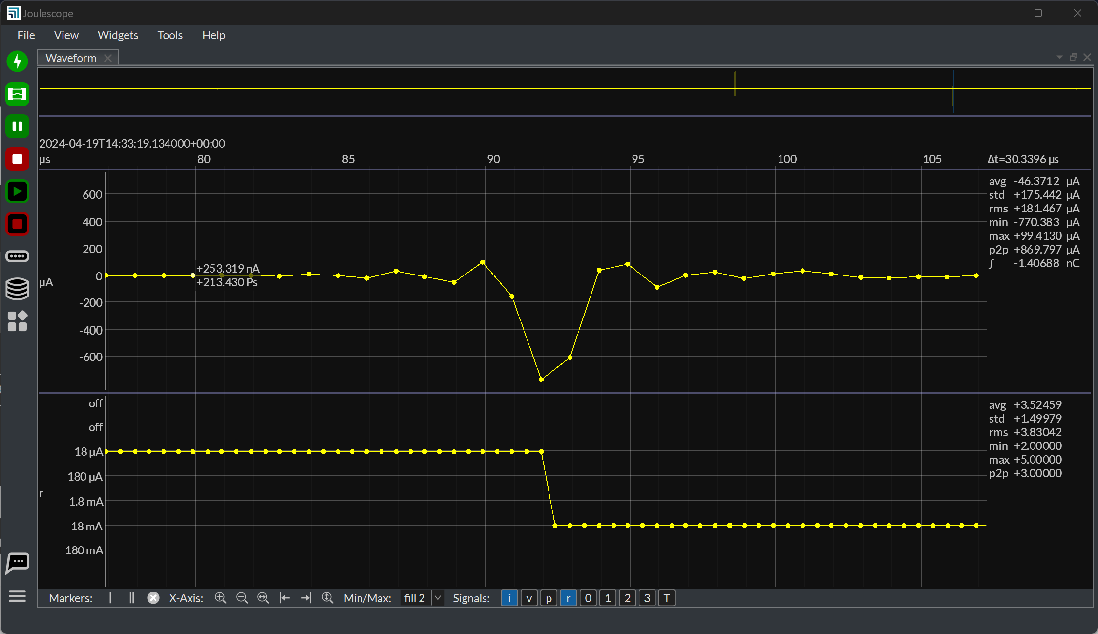
If I use a fixed current range then the waveform looks much as I expect, but I’m then missing out on one of the killer features.
Screenshots:
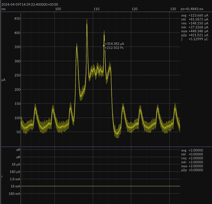
Fixed 18mA range (very conservative for 450uA peak current)
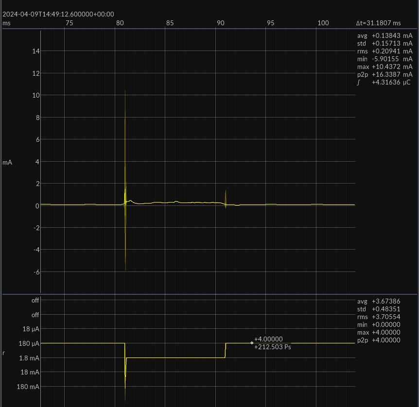
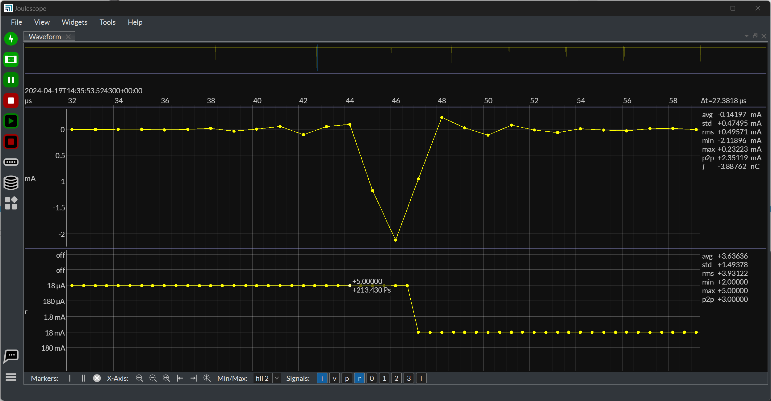
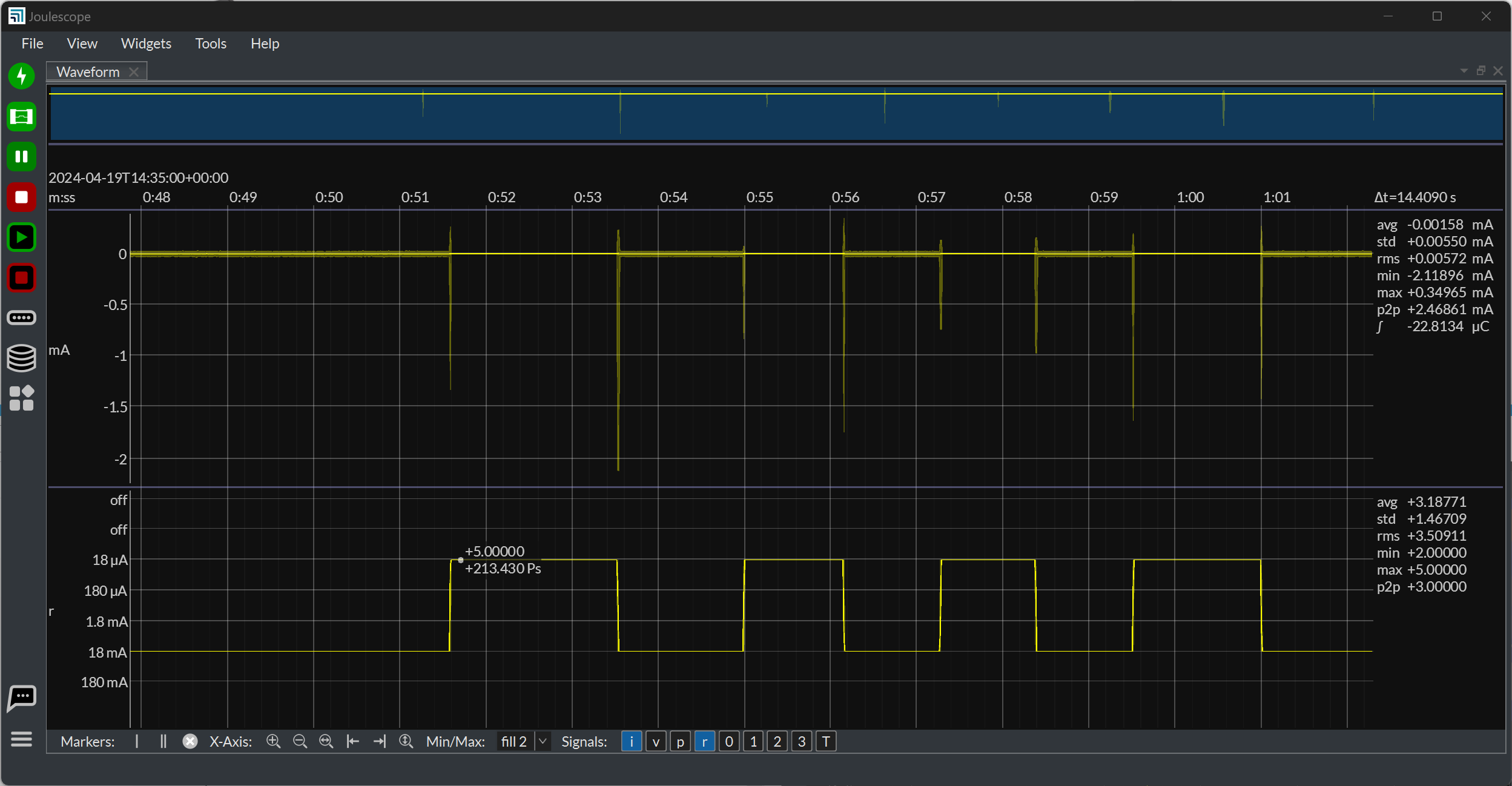
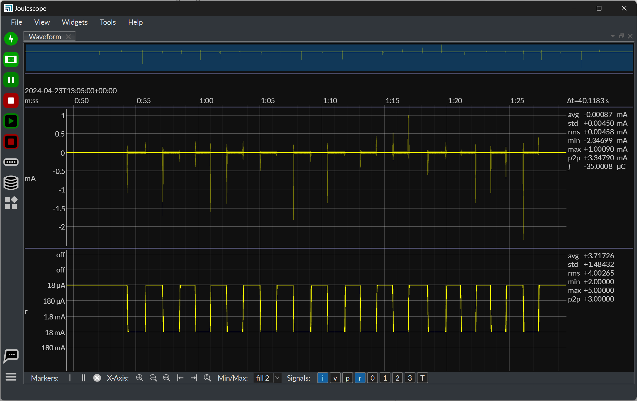
Using full auto range, 18uA - 10A
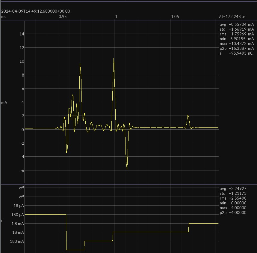
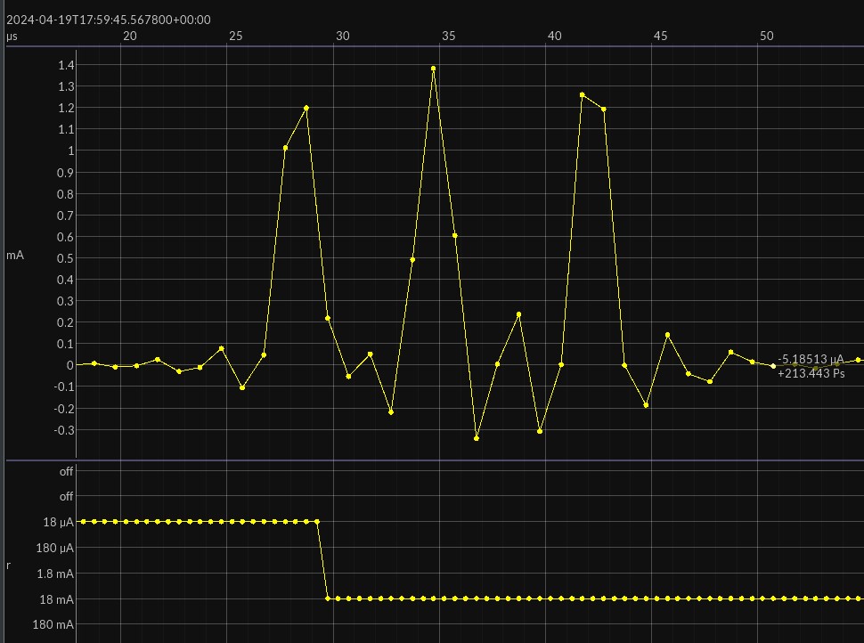
Zoom in on the first set of transitions
I understand the range switch will induce artefacts and even negative current flow, but this is rather larger than I was expecting. Even the negative spike is more than 10 times larger than the actual positive value. Am I being unrealistic in my expectation?
Simon
1 Like
Hi Simon,
You can constrain the current range. It looks like 18 mA may be enough for the top end here. By setting a lower maximum current range, you can also minimize switching artifacts. Use the Device Widget. You may need to use the 180 mA max range if 18 mA saturates.
Does this make sense and help your measurements?
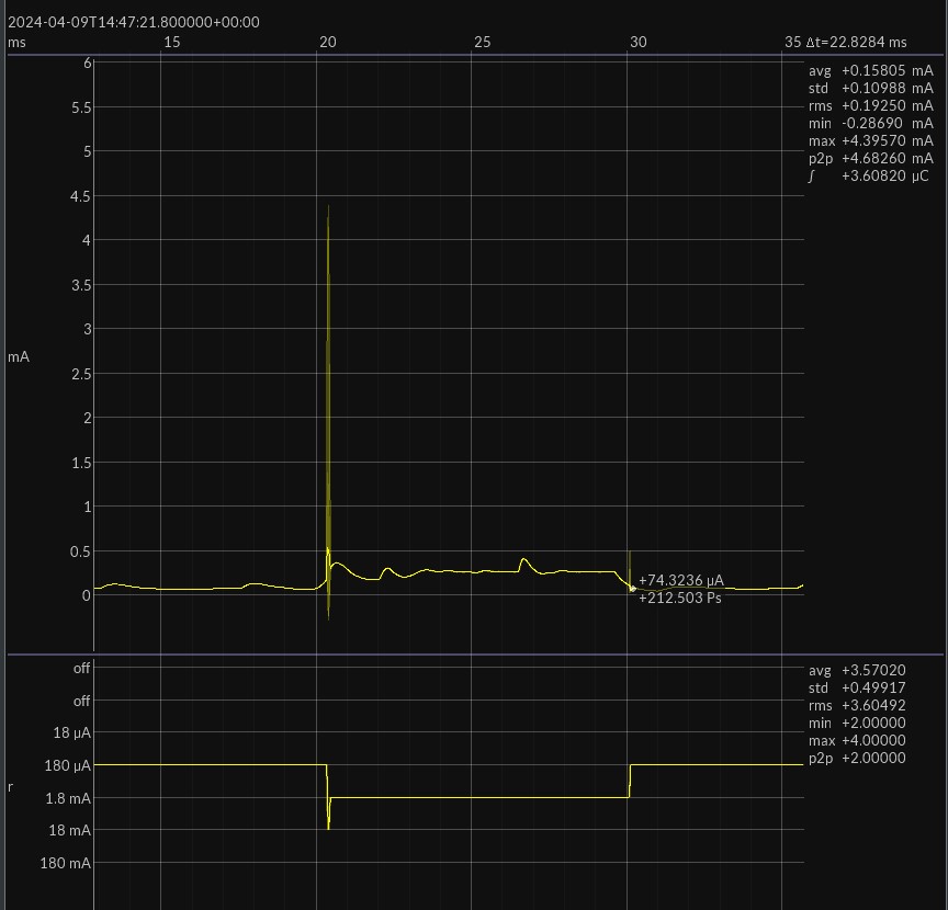
Yes, I understand that, and that’s what I did in the first screenshot. I have another screenshot which took me over the 3-image limit in the original post.
This one retains the 18mA upper limit, but allows the switcher to go down to the most sensitive range. The artifact is smaller but still almost 10 times bigger than the real signal. Also, if I use the 18mA fixed range, the noise in the low current areas is 10 times higher than it is when using the optimum range. The averaging line does a good job of showing the trend, but it’s rather defeating the point of having a high sample rate.
I was really hoping that having more than one converter and Enwavify would minimise these transients.
Your homepage says “Joulescope measures current and voltage 2 million times per second with 300kHz bandwidth. This high sampling rate makes the power consumption of interrupt service routines, inrush currents and other short events visible”. With CPU sleep currents in uA and ISR taking only a few microseconds, that’s not really possible with auto switching enabled. It’s still a great tool, but the advice that auto is the right mode for most situations doesn’t seem to hold.
Simon
Hi Simon,
Can you share a JLS file containing at least current and current range for that transition in the last post? For what you showed, I would only need 20 to 22 ms. You can post here or email support at joulescope dot com.
I apologize as I am at Embedded World and may not respond as quickly as usual.
Just to update the topic, I sent the file to support at joulescope dot com.
Hi @simonskirrid - I apologize for the delay. Embedded World was a great show, and my body is finally figuring out what time zone it’s in.
We investigated a number of things to try to duplicate what you are seeing. Unfortunately, nothing quite matches up. On current range changes, two things happen:
-
The Joulescope inserts a differet shunt resistance. Most targets have capacitance, which resists instananeous voltage changes. According to Ohms Law, V = I R. Assuming a constant supply voltage, V_supply = I * R_shunt + V_cap. Since V_supply and V_cap stay constant, instantaneous changes to R_shunt causes real additional current flow. This current flow is measured correctly by Joulescopes, but it is not really what you want to see. However, this current typically has a very visible RC time constant, which I do not see in your capture.
-
The Joulescope engages a MOSFETs to select appropriate new shunt resistor and then disengages the previous MOSFT for the prior shunt resistor, all in under 1 µs. We have very carefully designed Joulescopes to minimize parasitic effects involved in MOSFET switching, but you can never totally eliminate charge injection. We experimented with manually changing the current range from 18 µA to 18 mA on multiple Joulescopes from different manufacturing lots. We never saw more than approximately 2.5 mA spike for no more than 2 µs. The spike amplitude is sharper when it aligns perfectly with a sample. You are observing a much longer spike.
I would like to separate out the MOSFET charge injection from anything else going on in your system. Here is how:
- Disconnect your JS220 I+/I- terminals.
- In the Joulescope UI, select the Oscilloscope View with the Waveform widget.
- Enable the
i and r channels in the Waveform widget and in the Device Control widget.
- In the Device Control widget, select Current range
18 µA.
- In the Device Control widget, select Current range
18 mA.
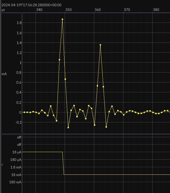
- Pause streaming. Zoom in on 18 µA to 18 mA transition and post a screenshot.
- Short JS220 I+ to I- using a wire.
- Repeat 4-6.
Here is an example from JS220 S/N 002557 with I+/I- shorted:
And open (the worse case):
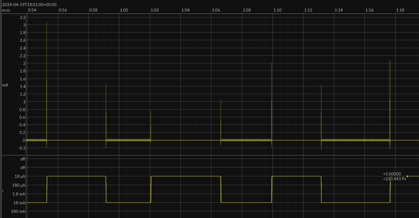
And manually toggling several times while open:
What do you see?
Hi Matt,
Thanks for getting back to me. This are what I see for those conditions:
I+/I- shorted
I+/I- open
Open and manually toggled
Simon
Hi @simonskirrid - Those wiggles look different than the wiggles I see. I currently have no explaination for why you would see multiple spikes for a single transition.
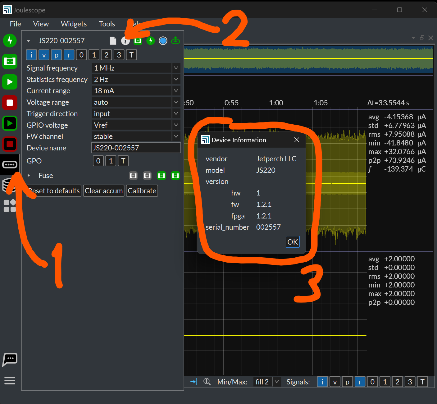
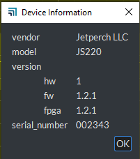
Can you confirm that you have the FPGA and FW versions 1.2.1? Here is how:
Hi @simonskirrid - Thank you for the update. We have performed additional testing, and we still do not understand what could cause what you observe. I would like to send you a replacement Joulescope and get the instrument you have back for further investigation.
Here is the behavior of JS220-002286, the instrument we plan on sending you:
All the transient pulses are a single pulse only ~3 samples wide.
I will send you a DM momentarily to coordinate shipping.