Hi @inlevis - It does not look like connecting Vref made much difference. It tends to get very, very weakly pulled to 3.3V, so it was probably working correctly originally.
Summary
The JS220 FPGA packs bits in a little-endian order, but the host software (as of Joulescope UI 0.10.13) unpacks bits in big-endian order. We need to fix the host software.
We are currently working on the next major Joulescope UI release that also completely changes how data is processed. We will test this release to make sure the GPI edges do not have glitches.
Investigation
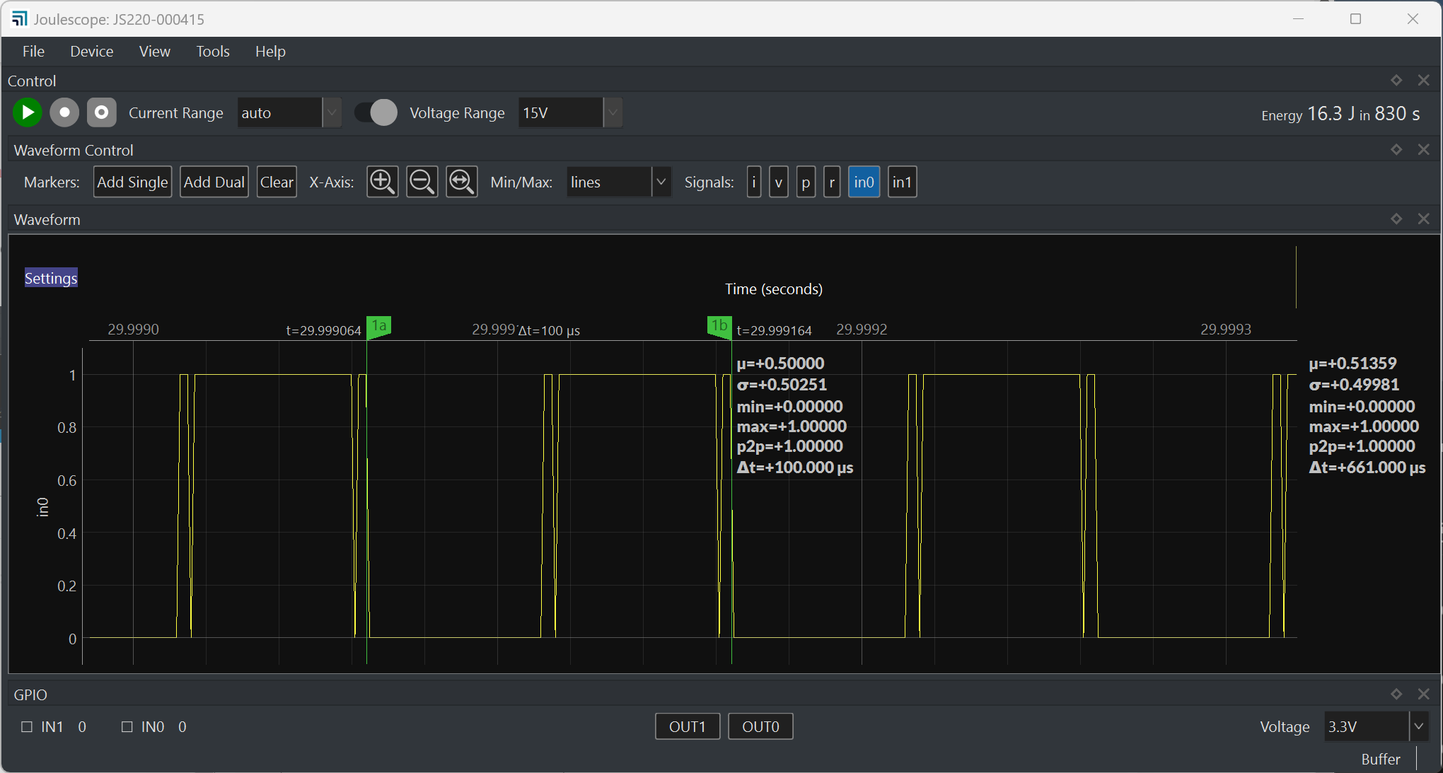
I took a closer look. I configured the JS220 EVK to output a 10 kHz square wave:
from machine import Pin, PWM
from evk import Pins

Pin(Pins.EXT0, Pin.OUT, value=0)
Pin(Pins.EXT1, Pin.OUT, value=0)
Pin(Pins.EXT2, Pin.OUT, value=1)

p = PWM(Pin(Pins.EXT0))
p.freq(10000)
p.duty_u16(0x8000)
Using the provided JS220 GPIO cable harness, I then connected:
- EVK.EXT0 to JS220.IN0
- EVK.GND to JS220.GND
- EVK.EXT2 to JS220.Vref
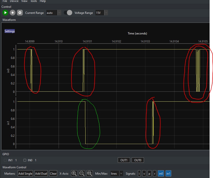
Here is what the Joulescope UI 0.10.13 displays with JS220-000415:
which seems pretty close to what you see.
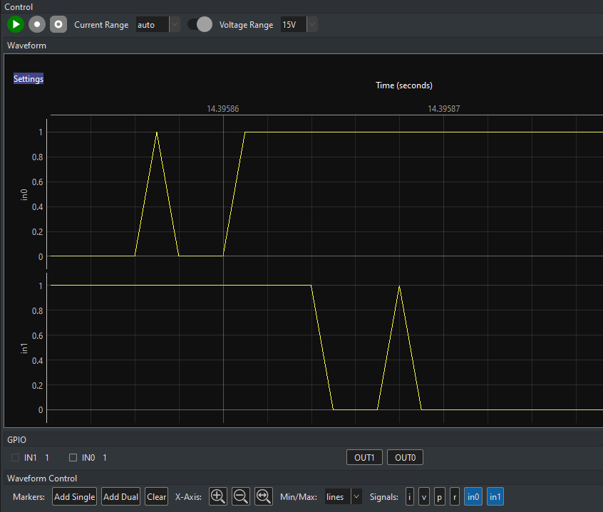
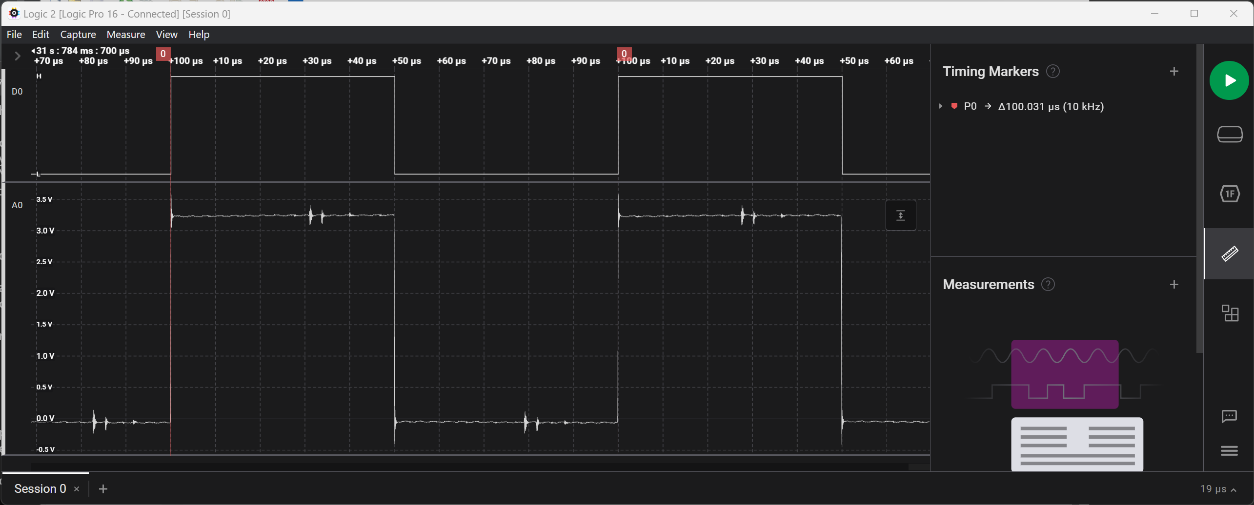
I then slightly unplugged the cable harness from the JS220 GPIO connector so that I could probe the bare metal for the connector pins. I probed IN0 using my Saleae Logic Pro 16, and it shows:
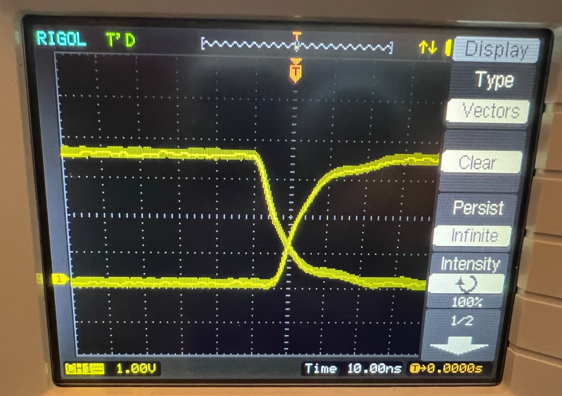
I definitely have a little noise in the setup, but the edge looks clean enough. I quickly confirmed the clean edges with my Rigol DS1102E bench oscilloscope:
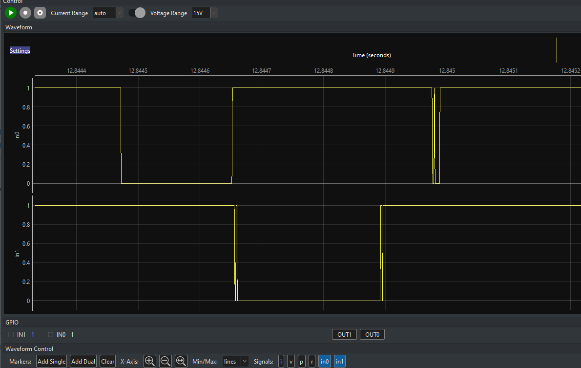
I then connected a bare JS220 main board PCB in the same configuration and measured the IN0 signal on the isolated side:
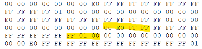
The edges look very clean. So it, looks like the glitches are caused by the digital processing, either on the JS220 FPGA or in interpreting the data. I inspected the USB traffic, and found edges like this:
The bits are in little-endian order. The host code unpacks them in joulescope.v1.sample_buffer, line 115 using data = np.unpackbits(data). However, this is big-endian by default. It should be data = np.unpackbits(data, bitorder='little'). Here is the fix.