Hi, I have a couple of questions about current range setting.
How can I set current range with pyjoulescope_driver?
I guess it’s given by --set, but I don’t know parameter. --help doesn’t give such detailed info.
(Where can I find info/document for all --set parameters?)
Is it possible to configure current range in runtime depending on GPIO state with pyjoulescope_driver?
Our device uses current ~70mA at peak and ~30uA at power down state (we’ll reduced it to < 10uA).
And auto current range doesn’t seem accurate enough for the power down state so that we need to change it to 180uA (eventually to 18uA).
First, you can list all parameters and values using
python -m pyjoulescope_driver info --open restore *
Add the “-v” option to also list the metadata, which includes the value options.
So, if you want to record at with the “18 mA” current range, you would do:
python -m pyjoulescope_driver record --set "s/i/range/select=18 mA" --set "s/i/range/mode=manual" out.jls
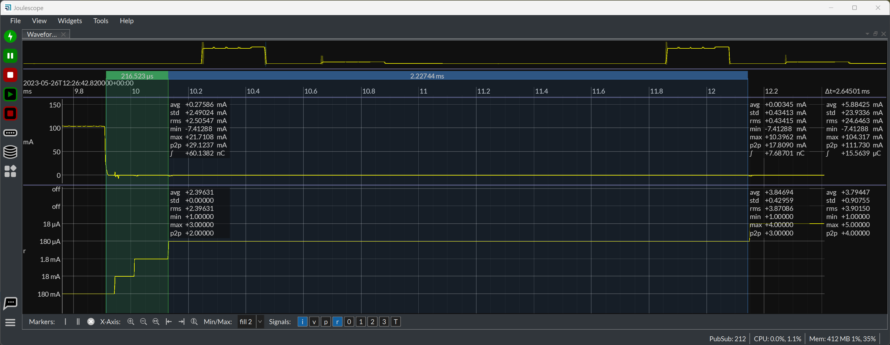
I supposed you could do something on the host, but the delay getting the GPI value through the JS220 over USB to the host and then sending the command to the JS220 would be MUCH longer than the autoranging delay to downrange from 10 A to 18 µA. It’s quite fast:
Let’s compute the charge offset error due to downsampling. Here is what I measure for downrange switching times in this case (consider as typical, not guaranteed):
Range
Duration
Error (µA)
Error (nC)
180 mA
25 µs
150
3.75
18 mA
68 µs
15
1.00
1.8 mA
118 µs
1.5
0.18
180 µA
2018 µs
0.15
0.30
Note that Error (nC) = Duration * Error (µA).
So the total error due to downranging from 180 mA to 18 µA is the sum of the Error (nC) volume, which is 5.23 nC. To compute the full error for a nonzero value, you can add ±0.25% of the actual value times the total downsampling duration of 2229 µs.
You can use this information to compute the percentage error for your application. Let’s say your device draws 70 mA for 100 µs, which is 70e-3 * 100e-6 = 7 µC. Your device then shuts down to 0 A. So, the error contributed by the JS220’s downranging is 5.23e-9 / 7e-6 * 100 = 0.075%. Seems pretty good to me
I wondered if it’s possible to configure joulescope to switch current range depending on gpio state before start capturing. It sounds not.
But is it possible for host to change current range after starting capture in the first place?
Why do you think it is not accurate enough?
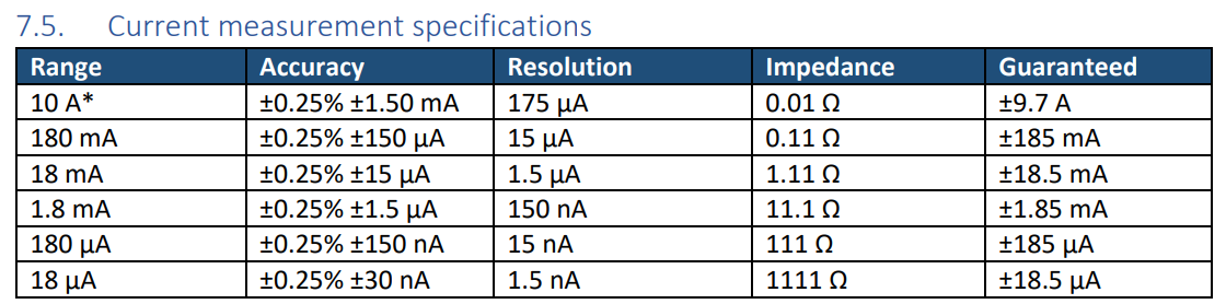
I see noisier wave at device’s power down state when using current range=auto and the noise was reduced when using low current range setting (=180 uA).
The python -m pyjoulescope_driver info --open restore info * should work, but you do need to be up-to-date:
pip3 install -U pyjoulescope_driver
Yes, the command for the JS110 is different:
python -m pyjoulescope_driver record --set "s/i/range/select=18 mA" out.jls
Yes, the host can change the current range parameters at any time, even during a capture. However, I would be VERY careful with setting manual current ranges as the JS110 and JS220 autoranging is designed to reach the best possible range. It is very easy to clip your signal by setting a manual current range.
It looks like you have turned off the min/max display on the waveform widget. You should have these on when using manual current ranging to ensure that you are not saturating. I suspect the reason that the Joulescope JS110 is not downranging is because the system has frequent activity above the current range threshold. If you set a manual range below this level, then you are clipping actual data.
You can see what autoranging is doing, if you want. Turn on the current_range = r channel in the waveform widget. The Joulescope UI 1.0 alpha now labels the current ranges on the y-axis and has a much nicer min/max display by default.
The python -m pyjoulescope_driver info --open restore info * should work, but you do need to be up-to-date:
Yes, it works after update it.
(Now I use pyjoulescope_driver 1.3.11, joulescope 1.1.5, jls 0.6.3, UI 1.0.17(alpha))
By the way, I cannot open jls file on UI 1.0.17. Is it expected? The file is captured by the UI.
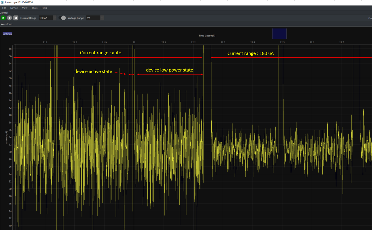
It looks like you have turned off the min/max display on the waveform widget.
I see that max is around 0.5 mA. That’s why auto doesn’t change curent range to 180 uA at low power state, isn’t it?
If you set a manual range below this level, then you are clipping actual data.
I wonder why max value is not saturated with current range=180 uA.
Unfortunately, 1.0.17 broke JLS v2 file open with some changes we made to pubsub. I just created issue #190. We also have a similar problem opening long JLS v2 captures. We are working to fix both these issues.
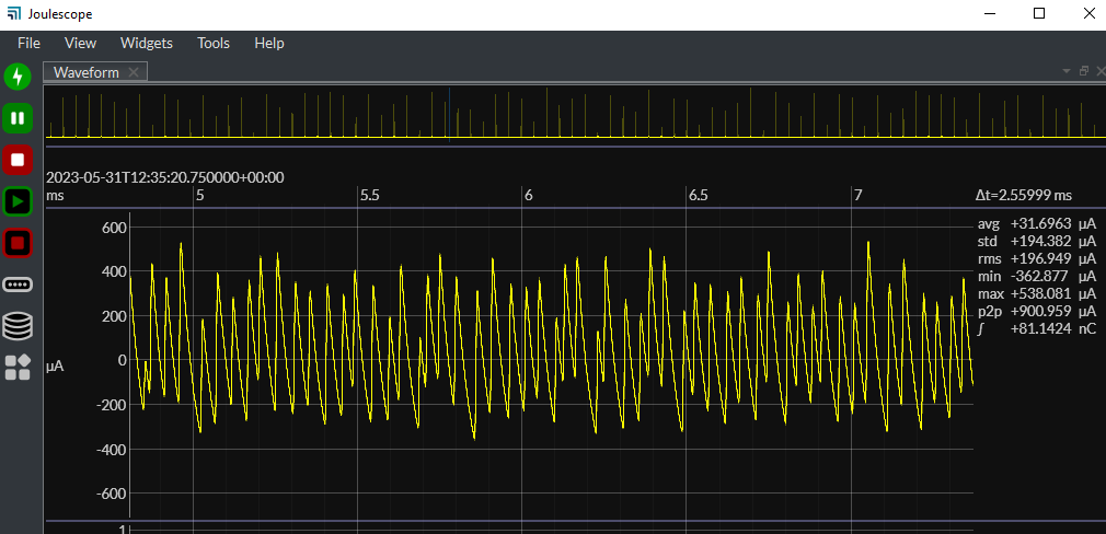
Yes. It looks like it stays in the 1.8 mA range and you have approximately 1 mA peak-to-peak noise. Are you measuring the input or output from a DC-DC converter? I suspect that you are seeing the current noise. Can you zoom into the “noise” region to see the signal?
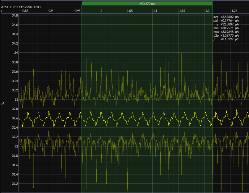
It does appear to saturate at offset 0.96 seconds in the most recent plot you showed. The peak looks to be 0.2 mA, which is about where the 180 µA range saturates. However, the noise is definitely lower. I suspect that the Joulescope’s series resistance is forming a low-pass filter with the target capacitance. In the 1.8 mA range, the Joulescope uses an 11.1 Ω shunt resistor. The 180 µA range uses a 111 Ω shunt resistor. This is likely reducing the system bandwidth which also reduces the noise.
However, if you are interested in accurately measuring the sleep current, you would ideally connect your system so that the Joulescope does not see this (likely DC-DC switching) noise. Can you share more information about your test setup?
This is likely reducing the system bandwidth which also reduces the noise.
I see.
We connect JouseScope at target device and connection is,
Host PC → adapter board (FTDI incl. DC-DC) → target device
I just tested by replacing the target device with a resistor (100k ohm) which represents resistance of power down state (30uA, 3.3V = 110k ohm).
Then I see much smaller noise and looks like DC-DC noise, I think.
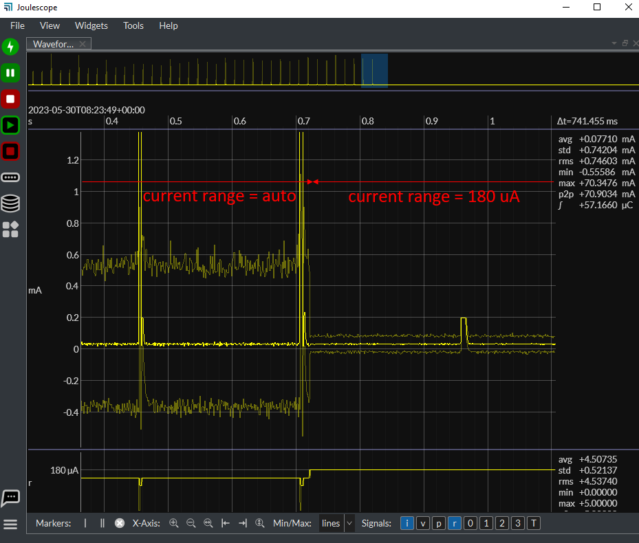
As you can see from the zoomed-in signal, the signal is 900 µA peak-to-peak, so the Joulesope JS110 will stay in the 1.8 mA range. If you want, you can add dual markers, right-click, select Analysis → Frequency to see more details about the DC-DC switching frequency characteristics.
What is your measurement goal? Is it to optimize the target device? You mentioned at the top that your device draws 30 µA in sleep, eventually targeting < 10 µA. The JS110 always operates at it’s full bandwidth of > 250 kHz. Within this bandwidth, you are using a power supply two orders of magnitude larger than your signal of interest. The JS110 will measure this setup accurately, but it may not meet your desired measurement accuracy.
The easiest solution is to simply reduce the power supply noise by using a lower noise supply, such as an LDO, at least for development.
If you cannot do that, you may be able to improve the existing DC-DC converter and/or reduce the system measurement bandwidth. I suspect that the DC-DC has limited output capacitance compared to the target board. This causes the switching ripple currents to flow to the target board rather than stay more local to the converter. You can add more capacitance or perform low-pass filtering, but you definitely need to know the DC-DC converter’s specs to ensure you don’t create even more noise.
What do you think? Can you use a lower-noise supply?