@mliberty feel free to move this to uncategorised or another category.
I’ve volunteered to convert the front panel designs to Kicad format (maybe someone has beaten me to it!). Although this should be relatively simple, I thought I’d see what other people thought would be useful front panel connectors to have. Maybe team Joulescope would be interested in your opinions and I might get some good ideas for my own custom panels (which I’ll be sharing as OSH). Either join in with the poll (preferably for ease of organisation) or add your non-conformist thoughts below!
IN: USB micro
IN: USB C
IN: 0.1" “Dupont” header pins/sockets
IN: JST lithium battery connectors
IN: Screw down binding posts
IN: XT60 battery connectors
IN: Some PTH you can solder your own cables to
IN: IDC etc (comment on pitch and pin numbers below)
IN: Other (comment below)
OUT: USB micro
OUT: USB C
OUT: 0.1" “Dupont” header pins/sockets
OUT: JST lithium battery connectors
OUT: Screw down binding posts
OUT: XT60 battery connectors
OUT: Some PTH you can solder your own cables to
OUT: IDC etc (comment on pitch and pin numbers below)
Good call. BTW, any preferences on directions of cable entry/exit? From/to the sides, the front or above? Thinking about the JST and dupont connectors, for example, which come in right angle versions.
No real preference. I think that the footprint for these Phoenix connectors (5.08mm / 0.2") matches multiple products, including the screw terminal type, the plug/socket type, and the Lever Actuated type.
Thanks @simonmerrett! Can I vote for all? I have received a few direct inquiries about USB C & USB 3. However, USB C & USB 3 means different things to different people:
USB C with the Power Delivery signals and just high-speed
USB C to USB A with super speed
USB C with all signals, including all 4 super-speed differential pairs
While (3) would be great to have, it probably requires controlled impedance fabrication which makes OSH sharing more difficult. You can get away with designing high-speed on a two-layer board, like the existing USB front panel.
Also note that USB Power Delivery 20V mode is beyond Joulescope’s measurement range. While Joulescope’s leakage current will increase, you won’t damage Joulescope until about 28.5 V (See the ESDLIN03-1BWY datasheet). Joulescope is definitely compatible with the lower voltage modes, but at least you won’t damage Joulescope if the host/device negotiates 20V.
The 5A modes are also beyond Joulescope’s 3A rating, but again it will likely work. The 0.01 resistor will dissipate 0.25 W, which is fine, but it will heat up enough to be slightly out of the advertised Joulescope accuracy spec.
Another thought: You could probably design a single front panel that supports JST, dupont, and PTH.
I am happy to accept pull requests to a new “kicad” subdirectory to the joulescope_front_panels repo. If want to do the design but not mess with git, send the design to me and I can commit for you (with credit of course!). I can also create links in the projects to your own repos/design if you would prefer to keep full control.
Yeah, I’m unlikely to go for option 2 or 3! Mainly the PD (cautionary note taken - and thanks for being up front about what’s possible if people want to push the boundaries) and basic HS lines.
I like @Philip’s point about just giving the 5.08mm pitch holes of suitable diameter and a bit of space and then people can add the terminal blocks they want to. If the hole is larger, you can always “fill it” with solder for smaller terminal block legs.
I was thinking a couple of days ago that I’d like to make a front panel with a linear regulator and a knob for setting the voltage (and maybe a disconnect switch so that you can set the voltage prior to attaching the DUT). You can use the readout through the software to set the voltage, then flip the switch to attach the DUT.
Why would I want this rather than just using one of my fancy bench supplies? Well, I haven’t started the thread on it yet but I’m seeing some weird behavior that I think is related either to the line inductance or possibly to the frequency response of my bench supplies. It’s possible that it’s neither, I haven’t worked it out yet, but it would be nice to eliminate that variable with a solid local regulator. It might be doubly nice to make it a 2 quadrant, because that may also be part of my problem. As a quick note, the problem I’m seeing is an inappropriate range change to the -2A range with a buck converter switching event, causing a ~-2uC glitch in my measurements that swamps my signal (my device is a BLE device with an average draw of ~10uA, confirmed through other reliable means, and I’m getting 40 of these -2uC glitches per second, so rather than reading 10uA I read -70uA, which is impossible anyway since my device doesn’t generate power from the aether).
@mliberty here comes the follow-up product! I can see a stacked-PCB mini power supply that you bolt-on sitting nicely in your product line-up. You don’t even need a display as that’s all on the PC GUI. Could Joulescope do hard on-off current limiting?
-2A is probably -1.2A or whatever it was (I’m going from memory right now). This isn’t related to the other issue and it does persist in 0.5.0. I haven’t had a chance to test the negative microamps issue again with 0.5.0.
And, yes, when I switched to the 180uA range the negative spike disappears and the numbers are more reasonable, however the resolution at 180uA seems to be limiting. My device spends almost all of its time drawing ~700nA.
I do plan to dig in a bit more on this issue and will make a new thread when I have more useful quantification of the problem.
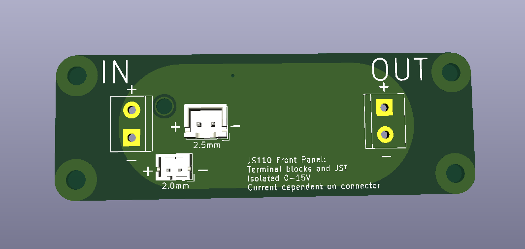
@NickLL@Philip how’s this for a starter for 10? Terminal block of your choice on 5.08mm / 0.2" pitch and two pitches of JST connector for lithium battery powered setups. What would you add/remove/change?
Looks like a nice start. My suggestion is to align everything a bit better.
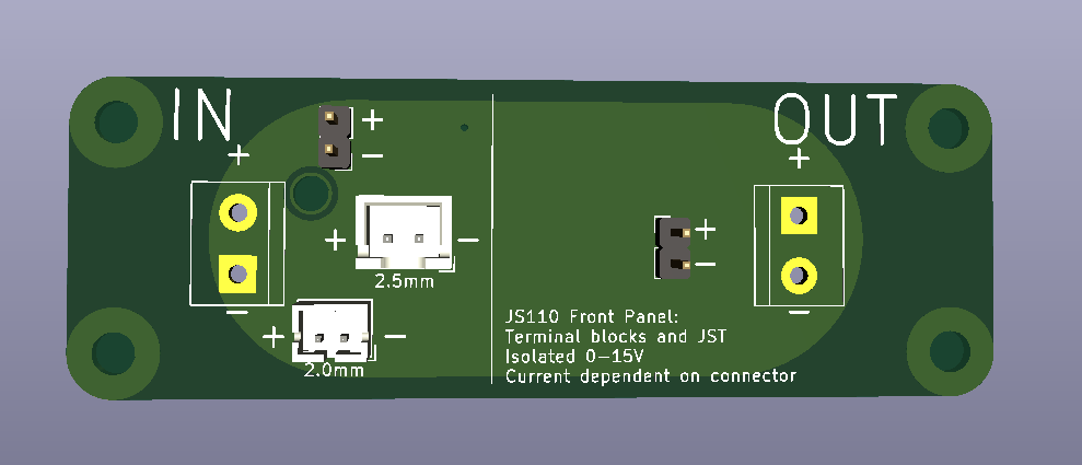
For example, you have pin 1 as the ‘-’ on the IN 0.2" header and pin 1 as the ‘+’ on the OUT 0.2" header. I understand that these match the connector well and if you were to swap it then one of them would be facing inward if the connector was installed correctly. My suggestion is to simply rotate them both 90 degrees. If your concern is that the wires coming out the top or bottom would be ugly, I’d suggest that they’d also be ugly coming out the left and right and that the best solution to that is to use vertical headers (like https://www.digikey.com/product-detail/en/phoenix-contact/1755736/277-1150-ND/260518).
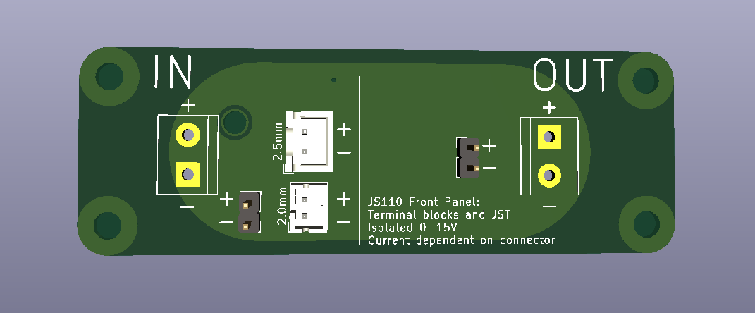
I would also suggest aligning all of the other connectors and making them all horizontally oriented (the 0.100" headers too) and horizontally aligned with each other, and all more toward the middle than the LED. It might look a little more cramped but that’s where the BNCs are placed and that looks fine. If you move all of the silkscreen labels to the side then you should have room to stack all 4 connectors on the left of the line, I think.
Thanks @NickLL, I get your point about alignment but I suppose I was mainly thinking about being able to grasp the connectors properly for removal, so tried to leave as much access around the sides as possible.
I’m not sure I agree about making the terminal block openings face up, rather than outwards but I’m glad to have your opinion. Hopefully others will voice theirs. It seems that if you populate both JSTs (optional if you don’t envisage using one of them) that a properly aligned vertical or horizonal layout would hinder fingers on one side or another, at least for the shallower of the two shrouds.
Edit - this makes me think we ought to have the shallower 2.0mm JST on top…