Recently I was using the Joulescope with a super capacitor between the scope and the given low-power circuit (with a battery as power supply) . The problem that I obtained is that measuring at the 18uA range (1111 ohm shunt resistor) will take up more then 3 hours to charge the capacitor (5τ = 5RC = 5* (1111+2*2.5)). This is not the problem, but forcing the Joulescope at the 18uA range ensures that the current draw stays 18uA for a long period of time, because the current draw is above this range for some time. Changing the current range (and also the shunt resistor) to the automatic mode makes the measurements too complex and fluctuating the whole time.
Is there any way to measure this setup properly? And how to deal with the super capacitor. It is working as a energy buffer, so in the end it won’t make a big difference for the battery lifetime.
Sounds like an interesting measurement, but I don’t think that I fully understand what you are trying to measure. I presume that you are doing some type of energy harvesting to the super cap, and want to measure the power contributions of each source: battery and energy harvesting. Is that right?
Joulescope’s 18 µA range with the 1111 Ω shunt will definitely affect the super capacitor charging and discharging, as you mentioned. If you select a fixed range, Joulescope measurement will max out, but the current across Joulescope’s shunt resistor may exceed the measurement range. For example, if you put 3.3V across Joulescope’s 1111 Ω shunt resistor, you will have 3.3/1111 = 3 mA, but Joulescope will only measure about 19 µA. The existing Joulescope JS110 is also not symmetric, and will only measure down to -4 µA in that range. This asymetry allows Joulescope to double is performance, but makes measuring both discharging and charging less accurate (or more difficult).
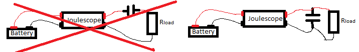
I’m going to assume you are trying to measure the contributions of energy harvesting and a battery. Do you have a way to connect one Joulescope on your battery and another Joulescope between all energy sources and your target load? That way, the energy harvesting & super cap can do its thing, and you can measure the total energy delivered to the target. You can then subtract out the battery to determine the energy harvesting.
Also, what is your maximum current of interest? Let’s say that you are only drawing 10 mA, max. Joulescope’s 18 mA range with only a 1.11 Ω shunt resistor gives you less than 15 µA offset error, which may be enough for this test without switching ranges.
The scenario is actually as simple as this. Where the the resistance of the microcontroller (Rload) does not change (+/- 2 Ohms). The capacitor (2.5F) needs a fixed shunt resistor to not be affected by the shunt resistor. This is actually a problem because of the measurement range is maxing out, just as you explained. The maximum current of interest is at about 10uA. I will consider the solution you described!
Hi @groj - Is the capacitor really in series with Rload as shown? You would normally have it in parallel unless you are trying to measure the capacitor leakage current.
Hi @Groj - ok, parallel makes sense. That 2.5F capacitor is really going to limit your system bandwidth. I normally recommend adding at least 10 µF capacitance to the load, but you have gone above and beyond
You mentioned:
How bad is it? Could you post a picture?
I would guess that the fundamental problem here is system bandwidth and very long time constants. Let’s say the device mostly draws 10 µA, but then turns on for long enough at some higher currents to drop 20 mV across Joulescope’s shunt resistor. When Joulescope autoranges to the 180 µA range, the shunt resistor changes from 1111 Ω to 111 Ω. This results in a very prolonged “inrush” event. Eventually the capacitor charges up, Joulescope autoranges back to 10 µA only to have this process repeat.
With that huge 2.5 F load, Joulescope’s 18 µA range with the 1111 Ω resistor gives you a system bandwidth of only:
f = 1 / (2 π R C) = 1 / (2 * π * 1111 Ω * 2.5 F) = 0.000057 Hz
Let’s look at the fundamentals. Say you want a 1 second time constant:
τ = R C
R = τ / C = 1 / 2.5 F = 0.4 Ω
Joulescope has 0.11 Ω in its 180 mA range, but ±150 µA specified offset error. You really want at least the 180 µA range with ±150 nA offset error (in practice much less, and you can manually confirm using no load before you run your measurement). This still gives 111 Ω for:
τ = 111 Ω * 2.5 F = 277.5 seconds, or about 5 minutes!
Even the 1.8 mA range is still τ = 28 seconds. If we could null out the offset error in the 1.8 mA range, would that work for your measurement?
It is really confusing, but as you said, measuring at the 180uA range may does the job .
So for now the only solution I think is measuring for long periods of time at the range of 180uA.
I can’t show the current range limitations for some reason now (I tried charging the cap overnight). But when it happens a straight line appears at +/-19uA in the range of 18uA.
Hi @Groj - thanks for the GIFs and images. That really helps! I think what you are seeing is the effect of the voltage across the shunt resistor combined with that super cap load. When you change shunt resistors, the shunt resistor voltage changes, which causes the capacitor to charge or discharge, and the time constants are VERY long.
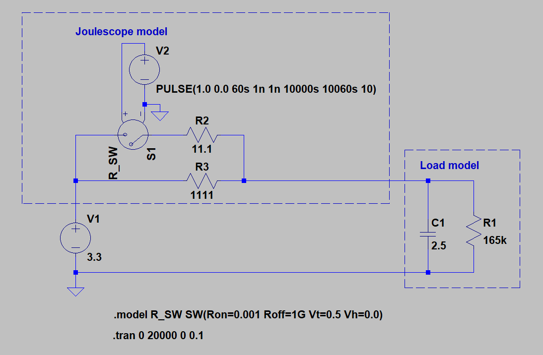
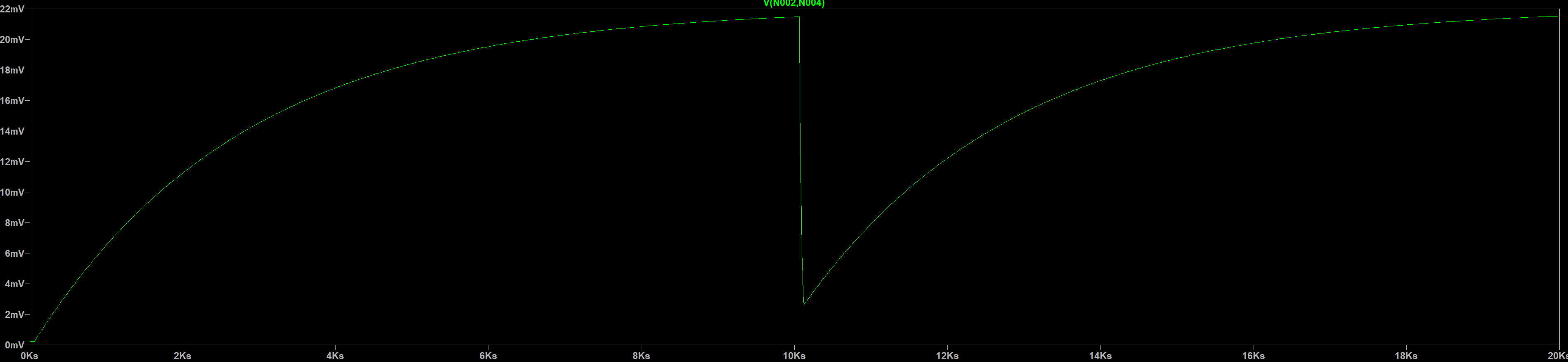
Here is an LTSpice model that emulates your system:
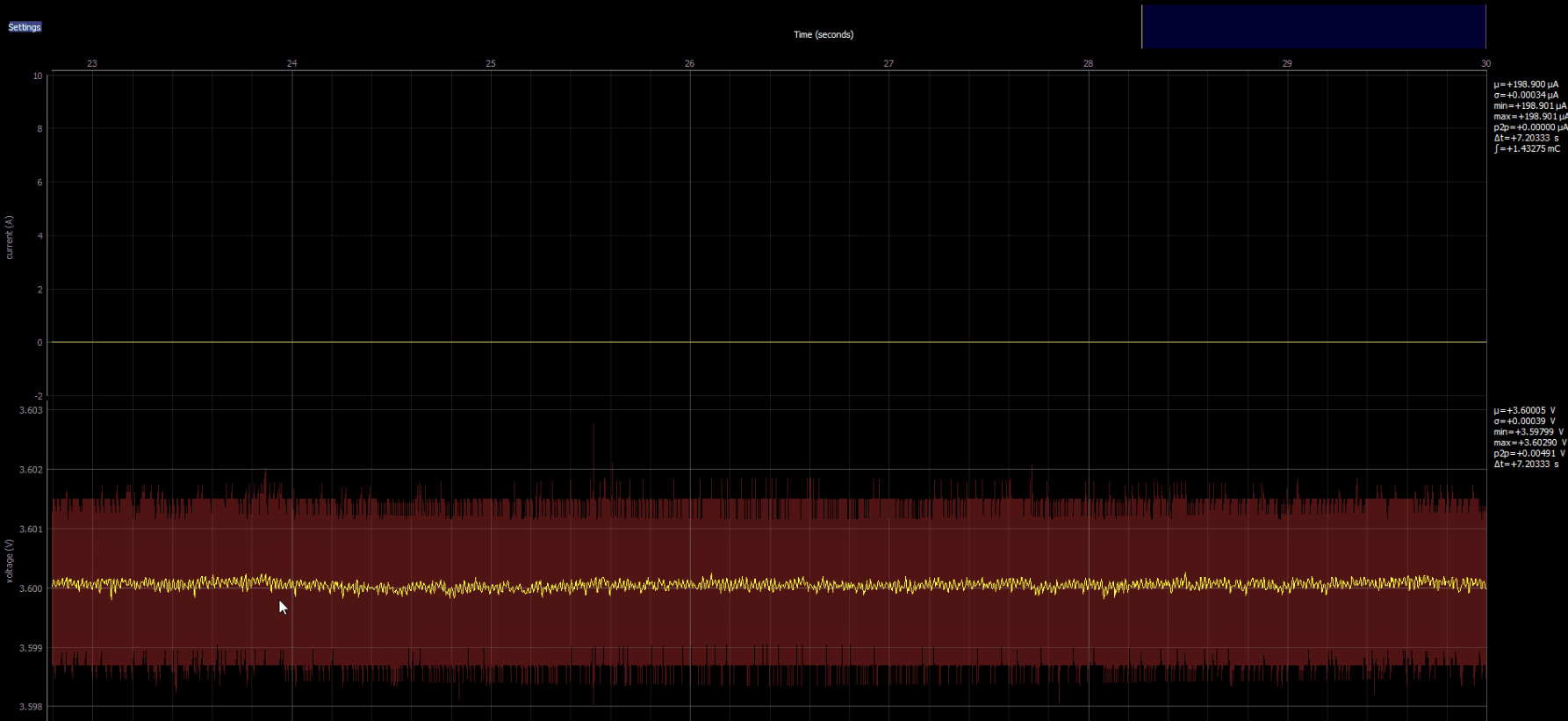
Note that the x-axis is in seconds. That’s 10K seconds, or nearly 3 hours!
The total energy calculated by Joulescope will still be correct, but due to the massive time constants, the current plot really doesn’t make intuitive sense.
Due to the extremely low system bandwidth, you can probably manually select the current range for your system, which sounds like 180 µA. If you end up seeing that the current exceeds 180 µA at any time, you will have to select the next range up (1.8 mA). When the current exceeds Joulescope’s measurement range while in a manually selected current range, you will see a flat line at just over the rated current for that range.